Fusion splicing device and fusion splicing method

Inactive Publication Date: 2005-11-22
SUMITOMO ELECTRIC IND LTD
View PDF9 Cites 8 Cited by
  • Summary
  • Abstract
  • Description
  • Claims
  • Application Information

AI Technical Summary

Benefits of technology

[0009]The present invention provides a fusion splicing apparatus for fusion splicing end portions of optical fibers by butt discharging, characterized by comprising an image observing mechanism for observing the end portions of the optical fibers, an image processing section for measuring parameter data of a brightness distribution waveform of optical fiber in cross section from a picked up image, a fuzzy operation section for obtaining a degree of attribution for the meas

Problems solved by technology

However, the type of the optical fiber may be mistaken, in which there is the risk that a splicing failure occurs due to unsuitable fusion splicing conditions for the optical fibers.
To make splicing again, a series of operations, including the removal of a falsely spliced portion, the removal of the coatings for the end portion of optical fiber and cutting the end portion must be performed from the beginning, resulting in a worse working efficiency, and the operator becomes nervous.
However, when the type of optical fiber is estimated by obtaining the brightness profile from an observed image of the optical fiber, there are various intricate factors such that the brightness profile may be varied or different between the same type of optical fibers, depending on the focus or optical characteristics of the observed image, and the manufacturing conditions of the optical fiber.
Hence, the resolution can not be sufficiently obtained, whereby it is difficult to acquire the detailed information from the brightness profile.
Even if image observing means with high magnification and high resolution is employed for image observation, a DS fiber and an ED fiber, for example, have both a core diameter of 4 μm, with quite similar brightness profiles, and practically is difficult to discriminate from the comparison between the brightness profiles.
Accordingly, although this technique is effective when the brightness profile is clearly different depending on the type of optical fiber, it is difficult to discriminate all the types of optical fiber.

Method used


Image

  • Fusion splicing device and fusion splicing method
  • Fusion splicing device and fusion splicing method
  • Fusion splicing device and fusion splicing method

Examples


Embodiment Construction

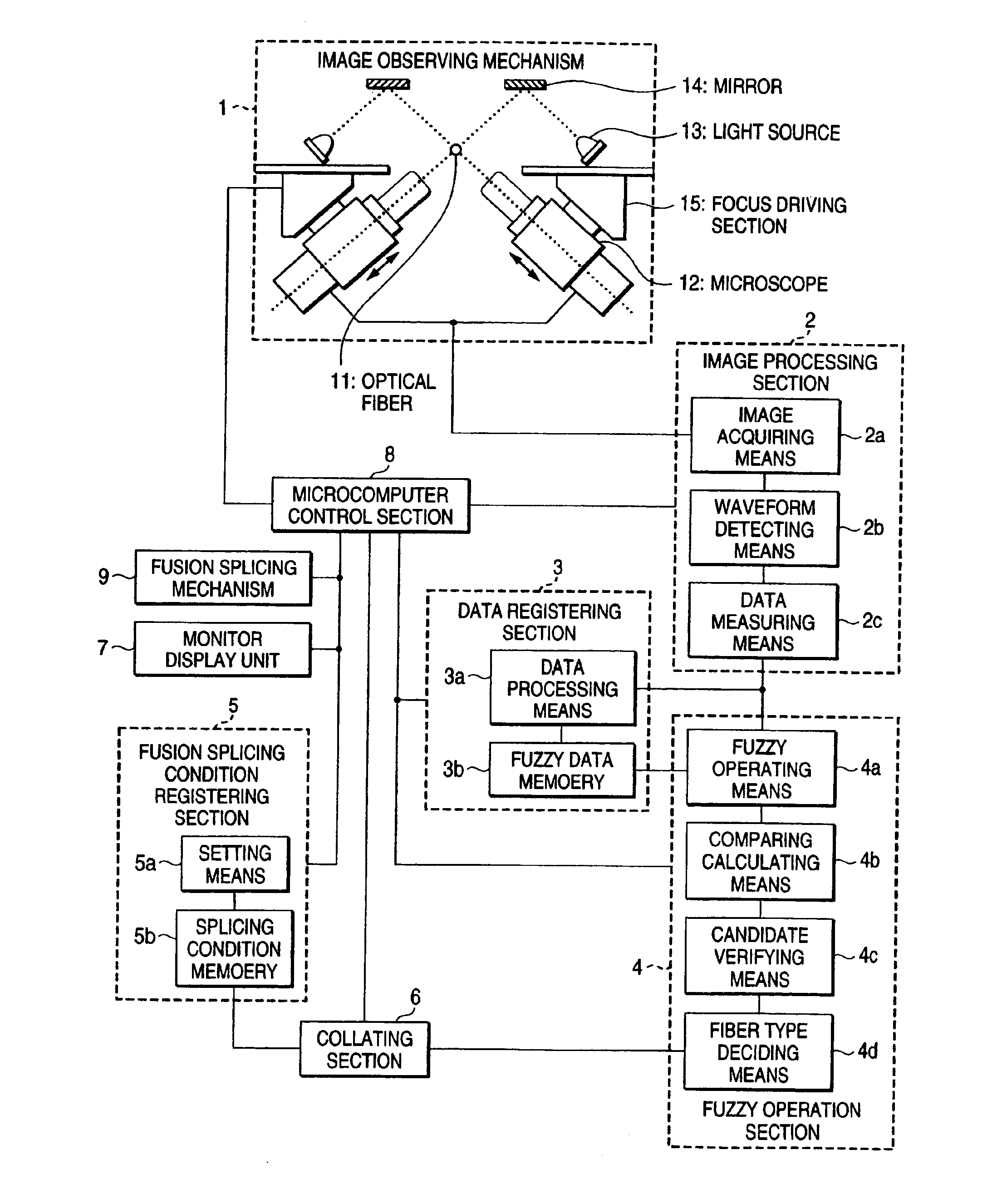
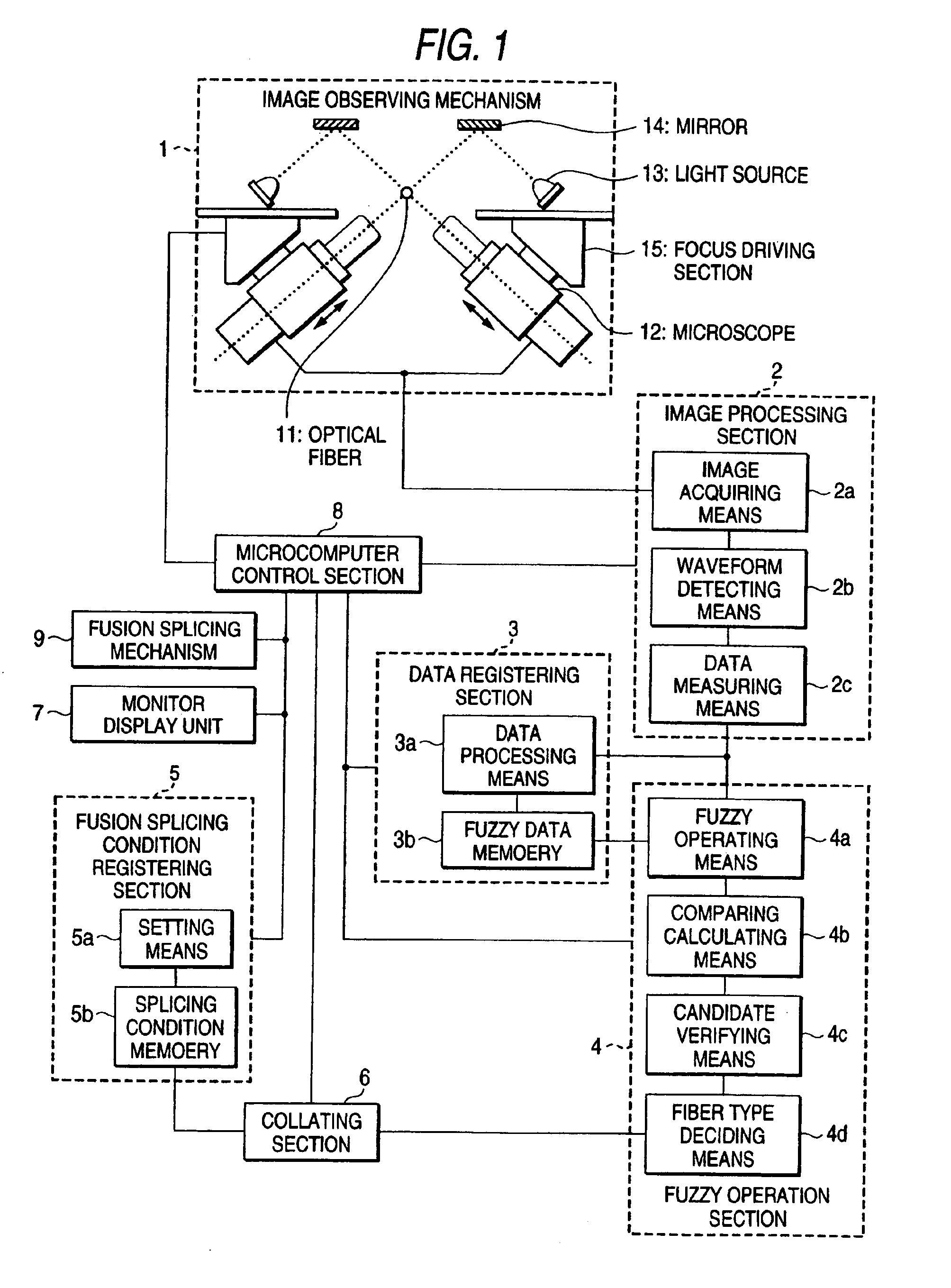
[0021]FIG. 1 is a block diagram for explaining an embodiment of the present invention. In FIG. 1, reference numeral 1 denotes an image observing mechanism, 2 denotes an image processing section, 3 denotes a data registering section, 4 denotes a fuzzy operation section, 5 denotes a fusion splicing condition registering section, 6 denotes a collating section, 7 denotes a monitor display unit, 8 denotes a control section, 9 denotes a fusion splicing mechanism, 11 denotes an optical fiber, 12 denotes a microscope, 13 denotes a light source, 14 denotes a mirror, and 15 denotes a focus driving section.

[0022]The image observing mechanism 1 picks up an image of a pair of optical fibers 11 butted and held by the fusion splicing mechanism (not described in detail and not shown) from two directions using the microscopes 12 with the CCD cameras disposed orthogonal to each other. The light source 13 for illumination to pick up the image is disposed to illuminate the optical fiber 11 via the mirr...


PUM


Abstract

A fusion splicing apparatus for fusion splicing end portions of optical fiber by butt discharging. Parameter data of a brightness distribution waveform of optical fiber in cross section is measured from a picked up image. A degree of attribution for the measured parameter data is obtained from fuzzy operation data registered in advance, and the type of the optical fiber is identified through a fuzzy operation. The identified type of the optical fiber is collated with fusion splicing conditions for type of optical fibers registered in advance. The collation result is displayed.

Description

FIELD OF THE INVENTION[0001]The present invention relates to an apparatus and method for fusion splicing end portions of optical fibers for communication by discharge heating and the like, and more particularly to an apparatus and method for fusion splicing the optical fibers under fusion splicing conditions suitable for types of optical fibers by automatically determining the types of optical fibers.BACKGROUND OF THE INVENTION[0002]Along with the expansion and diversification of the optical fiber communications in recent years, various types of optical fibers adapted for respective uses have been developed and utilized. Various types of optical fibers, including a single mode optical fiber (hereinafter referred to as an SM fiber), a multi-mode optical fiber (hereinafter referred to as an MM fiber), a dispersion shifted optical fiber (hereinafter referred to as a DS fiber), and an erbium doped optical fiber (hereinafter referred to as an ED fiber), are provided. When these optical f...

Claims


Application Information

Patent Timeline
IPC IPC(8): G02B6/255G02B6/38
CPCG02B6/2551G02B6/2553G02B6/2555G02B6/255
Inventor HATTORI, KAZUNARI
Owner SUMITOMO ELECTRIC IND LTD
Why Eureka
Try Eureka