Cutting tool and track guidance system

a cutting tool and track guidance technology, applied in the direction of manufacturing tools, locomotives, metal working apparatuses, etc., can solve the problems of large and complicated machining loads, limited tools, and inability to meet the needs of large-scale and complex tool support assemblies, and achieve high machining loads, high machining loads, and quick attachment and removal.

Active Publication Date: 2005-11-22
TRI TOOL INC
View PDF33 Cites 47 Cited by
  • Summary
  • Abstract
  • Description
  • Claims
  • Application Information

AI Technical Summary

Benefits of technology

[0010]The present invention provides a cutting tool and track guidance system for cutting workpieces that are flat as well as arcuate. The cutting tool

Problems solved by technology

Normally, a single-point tool is fed around and into the pipe repeatedly to remove a small amount of material each pass until the pipe is cut through, which in the case of a thick wall may consume a considerable amount of time.
In conventional pipe cutting tools, it is a challenge to locate and support the cutting tool so that smooth and true machining operations can be performed at high tool loadings, while maintaining bearing assemblies free of gross contamination such as chips generated during the machining operation.
High radial and thrust loads are encountered durin

Method used


Image

  • Cutting tool and track guidance system
  • Cutting tool and track guidance system
  • Cutting tool and track guidance system

Examples


Embodiment Construction

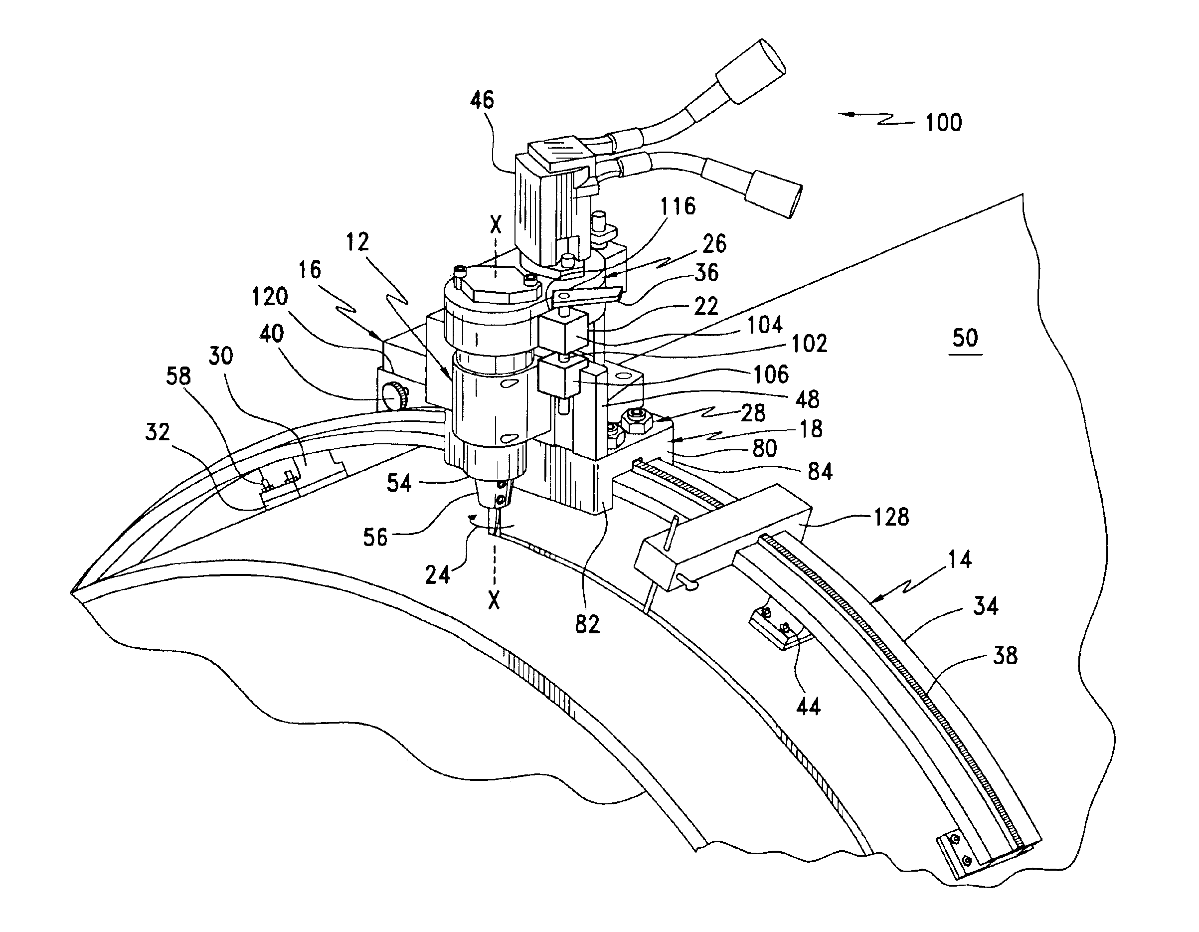
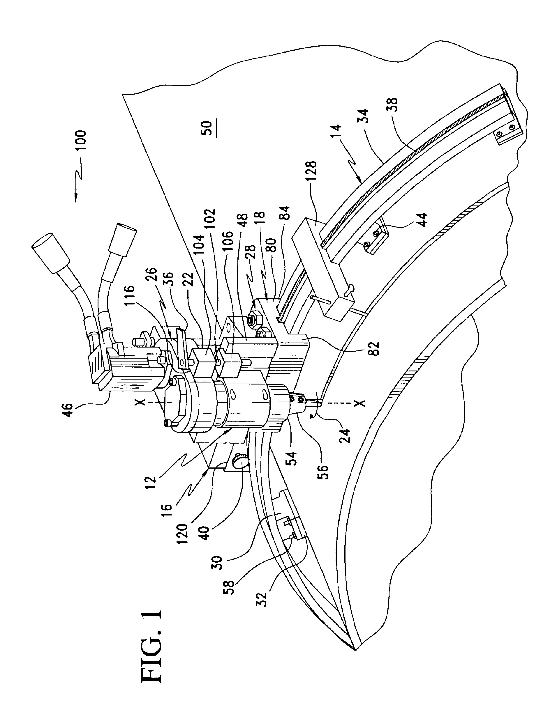
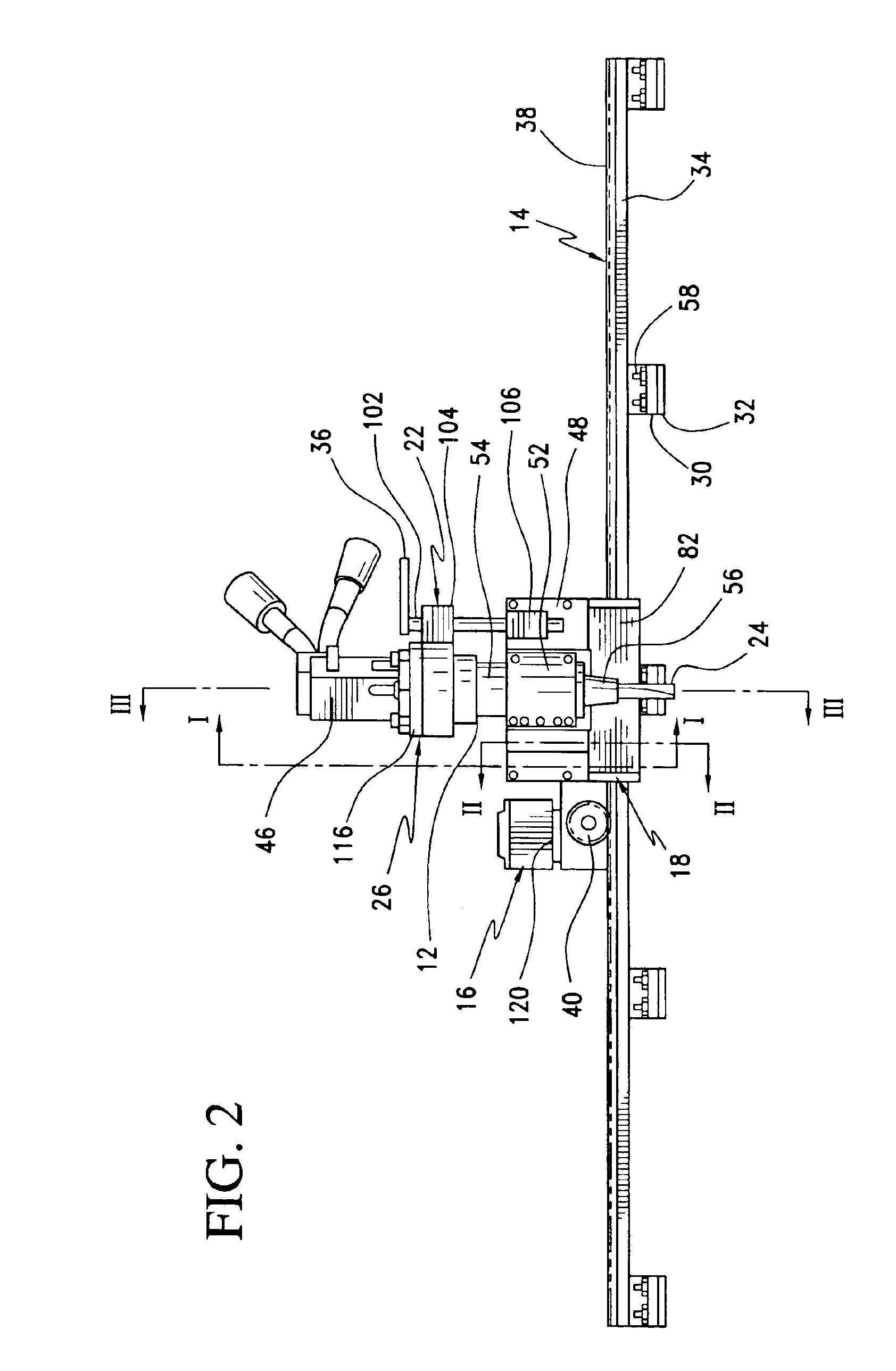
[0028]FIGS. 1-2 show views of a cutting tool and track system 10 according to a preferred embodiment of the invention. The cutting tool and track system 10 comprises a multi-segment track assembly 14 formed of multiple track elements arranged to support a carriage assembly 18 carrying a cutting tool assembly 12 and connected to a carriage drive mechanism 16 for displacing the carriage assembly 18 along the track assembly 14.

[0029]Referring to the embodiment shown in FIGS. 1 and 2, each track element includes a track member 34 that may be sufficiently flexible to generally conform to a workpiece having a curved surface. Preferably, the track member 34 is flexible to a degree that will permit the track member 34 to be directly bent to match the geometry of a workpiece. The track member 34 has top, bottom and side surfaces and preferably a substantially rectangular cross-section. The track member 34 is preferably constructed from flexible, high strength carbon steel.

[0030]A rack member...


PUM

PropertyMeasurementUnit
Thicknessaaaaaaaaaa

Abstract

A cutting tool and track system includes a multi-segment track assembly configured to be removably attached to a surface of a workpiece, a carriage assembly configured to ride along the track assembly, a carriage drive mechanism arranged to drive the carriage assembly along the track assembly, a cutting tool assembly connected to the carriage assembly, and a tool driving system connected to the cutting tool assembly. The cutting tool assembly rotatably supports an end mill type cutting tool that may be driven in a radial cutting plane about the axis of a tubular workpiece or along a workpiece surface. A method is provided for cutting a workpiece wherein a cutting tool assembly rotatably supports an end mill mounted for travel along a predetermined transport path in a cutting plane about a central axis of the workpiece wherein the end mill is first fed through the wall thickness of the workpiece and the cutting tool assembly is moved along the transport path in the cutting plane to cut the workpiece.

Description

[0001]This application claims the benefit of provisional application No. 60 / 450,699 filed Mar. 3, 2003.BACKGROUND OF THE INVENTION[0002]1. Field of the Invention[0003]The invention relates to a method and cutting tool and track system useful for cutting through a workpiece having flat or arcuate surfaces.[0004]2. Discussion of Related Art[0005]Numerous portable cutting tools are known in the art of cutting workpieces having flat and curved surfaces. In relation to cutting pipes, portable pipe cutting tools are typically used in the field where the use of a fixed machining tool is not appropriate or possible. Types of conventional pipe cutting tools include portable lathes such as one described in U.S. Pat. No. 4,418,591 or roller cutter modules such as one described in U.S. Pat. No. 5,515,756. Generally, conventional portable pipe cutting tools include a rotary tool head carrying a fixed or rotary cutting tool that is driven in rotation about an axis while otherwise fixedly supporte...

Claims


Application Information

Patent Timeline
IPC IPC(8): B23Q9/02B23Q35/00B23Q9/00B23Q35/10B23C3/00B23C3/34
CPCB23C3/34B23Q9/02B23Q35/102Y10T409/306384Y10T409/303808Y10T409/30644B23Q2210/008
Inventor VANDERPOL, JERALD W.LARSON, LANE L.
Owner TRI TOOL INC
Why Eureka
Try Eureka