Bearing pressure balance apparatus

a technology of bearing and pressure differential, which is applied in the direction of liquid fuel engines, vessel construction, marine propulsion, etc., can solve the problems of premature bearing failure, lubricant to leak from the bearing, and lubricant to leak into the fluid channel

Inactive Publication Date: 2005-11-22
HONEYWELL INT INC
View PDF17 Cites 28 Cited by
  • Summary
  • Abstract
  • Description
  • Claims
  • Application Information

AI Technical Summary

Benefits of technology

[0013]In a yet further aspect of the present invention, a method of compressing a gas without causing bearing lubricant leak, comprises flowing a gas into a compressor housing; applying aerodynamic resistance to the gas; directing the gas through and around a bearing; and directing the gas across an outer surface of a shaft.

Problems solved by technology

The volumetric gas flow passing through a centrifugal compressor creates a pressure differential across the compressor apparatus that may cause a pressure drop across the bearings, causing lubricant to leak from the bearing and premature bearing failure.
Leaking lubricant may leak into the fluid channel.
However, these labyrinth seals have needed to be pressurized and intricate in design to be effective.

Method used


Image

  • Bearing pressure balance apparatus
  • Bearing pressure balance apparatus
  • Bearing pressure balance apparatus

Examples


Embodiment Construction

[0018]The following detailed description is of the best currently contemplated modes of carrying out the invention. The description is not to be taken in a limiting sense, but is made merely for the purpose of illustrating the general principles of the invention, since the scope of the invention is best defined by the appended claims.

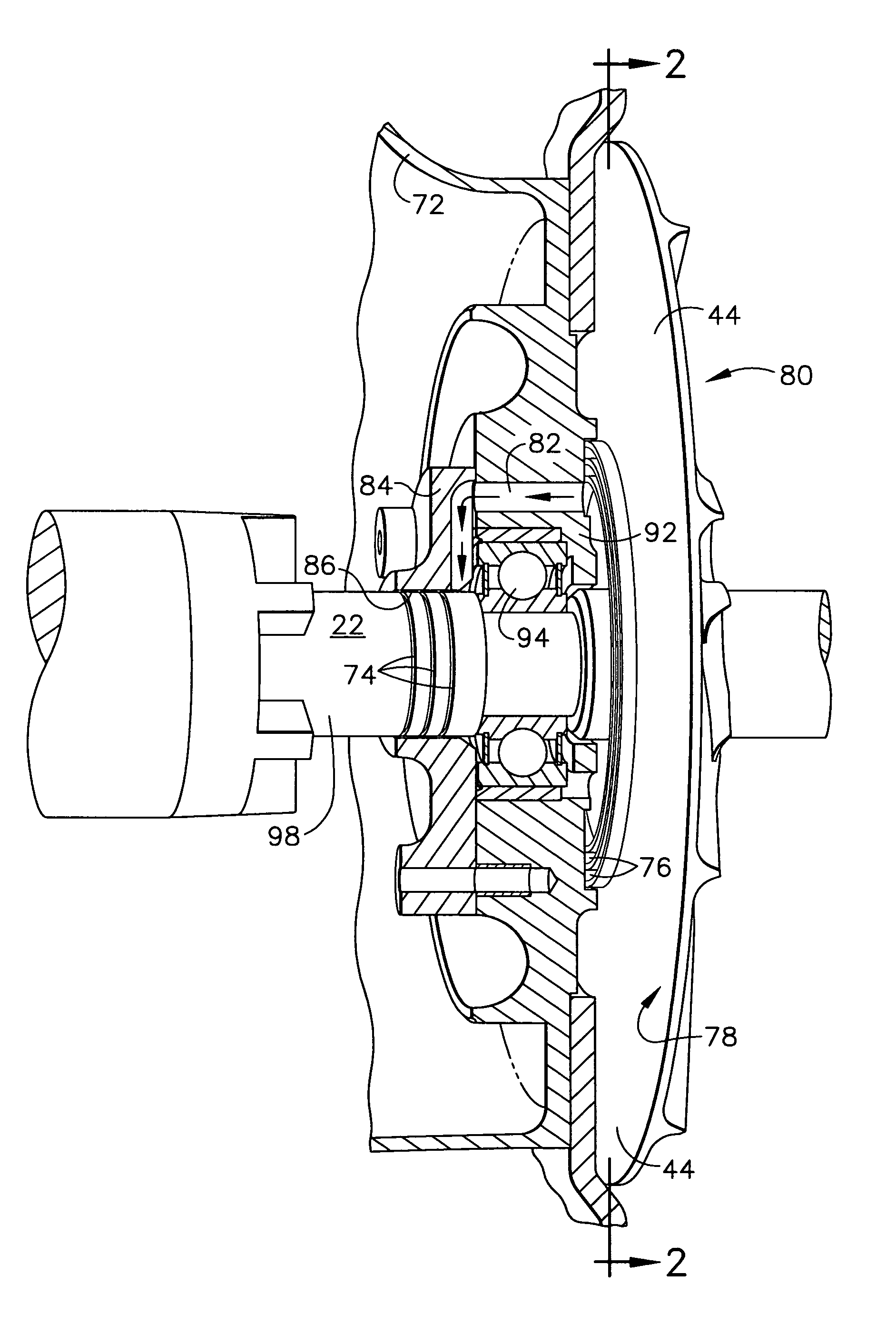
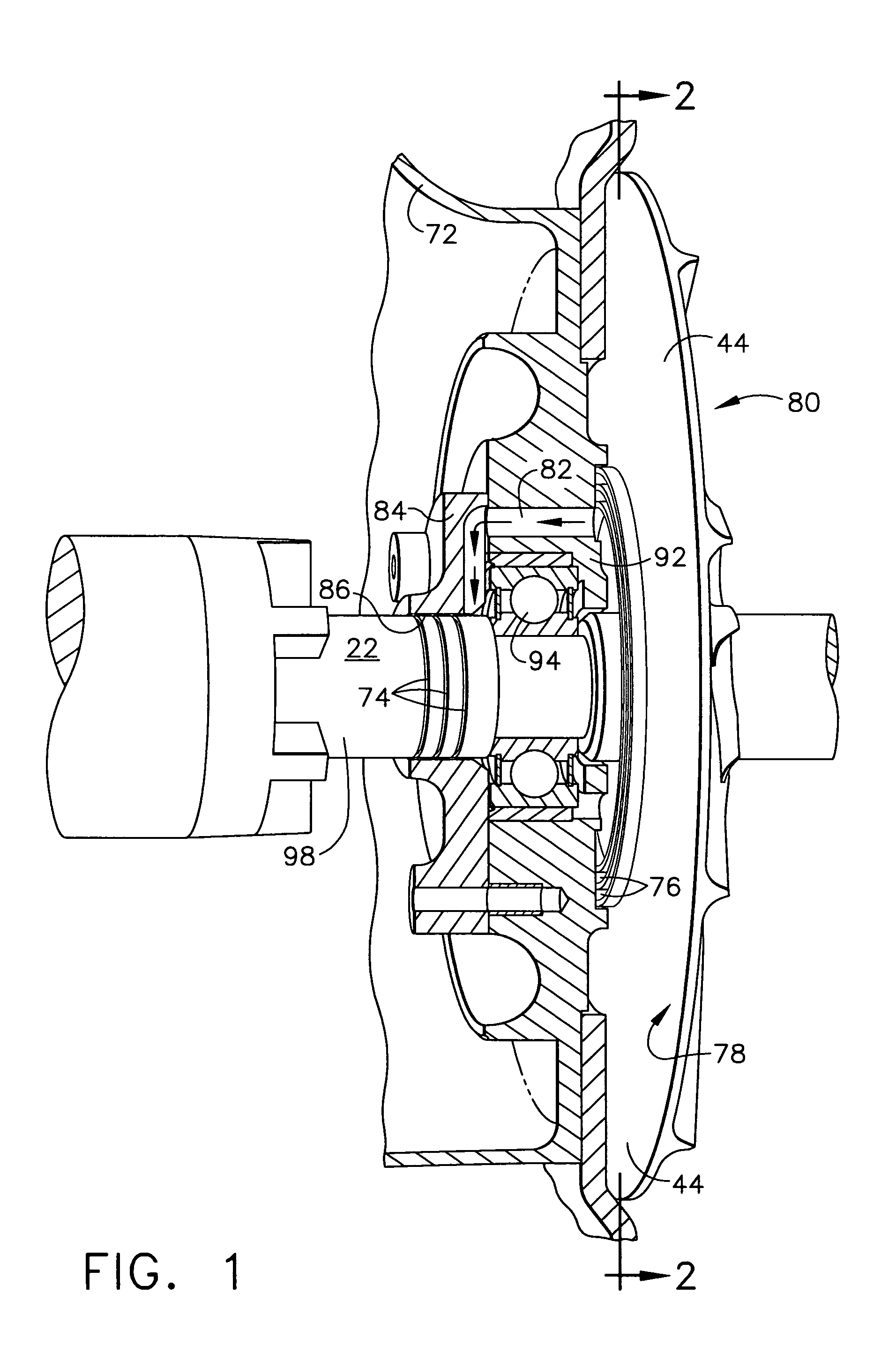
[0019]The invention is useful for aircraft, spacecraft, military vehicles, and other vehicles. Specifically, the invention is useful for auxiliary systems, such as pneumatic equipment for pressurizing tanks, transferring fuel (e.g., refueling operations), generating vacuum (e.g., sanitation systems), and other processes. The invention is also useful for turbochargers. For illustrative purposes, the following description is of a compressor housing, however, it is to be understood that other applications can be substituted for the compressor housing.

[0020]The present invention may protect the bearing from lubricant migration by eliminating pressure differ...


PUM


Abstract

The present invention provides a method and apparatus for balancing the pressure across a front bearing in a compressor housing. The present invention may protect the bearing from lubricant migration by eliminating pressure differentials across the bearing. When a blower or fan is running, the bearing experiences the same pressure differential that is across the blower. Unless this pressure is balanced, lubricant may migrate from the bearing very quickly. The present invention may provide a pressure balance and sealing across the front bearing of a blower or fan. A plurality of grooves on the face of a compressor impeller and a plurality of grooves on a compressor shaft surface restrict the gas flow to balance pressure across a bearing. Alternatively, a labyrinth seal may cooperate with a plurality of grooves on the face of a compressor impeller to balance pressure across the bearing.

Description

CROSS-REFERENCE TO RELATED APPLICATIONS[0001]This application claims the benefit of U.S. Provisional Patent Application No. 60 / 435,327, filed on Dec. 19, 2002.BACKGROUND OF THE INVENTION[0002]The present invention relates generally to centrifugal compressors and, more specifically, to a method and apparatus for balancing a pressure differential across a bearing.[0003]Turbines may use the exhaust gasses discharged from internal combustion engines as a motive gas to rotate a turbine wheel that may be mounted on one end of a shaft. An impeller may be mounted on the other end of the shaft, and is turned by the turbine wheel to compress gas, which then may be communicated to the engine, thereby supplying charge gas to the engine for increasing engine performance. To improve operating efficiency and to extend range or operation, it may be desirable to control the flow of gasses and control pressure drop across a bearing.[0004]Aircraft, spacecraft, military vehicles, and other vehicles dep...

Claims


Application Information

Patent Timeline
Patent Type & Authority Patents(United States)
IPC IPC(8): F04D29/04F04D29/06F04D29/051F04D29/059
CPCF04D29/051F04D29/059F04D29/063F16C19/52F16C19/06F16C2360/46F04D29/0516
Inventor CARDENAS, ALFREDOMCKELVEY, WILFRED G.
Owner HONEYWELL INT INC
Why Eureka
Try Eureka