Operation apparatus with auto correction of position data of electric faders

a technology of position data and operation apparatus, which is applied in the direction of computer control, control mechanism, program control, etc., can solve the problems of affecting the accuracy of detection

Active Publication Date: 2005-11-22
YAMAHA CORP
View PDF19 Cites 32 Cited by
  • Summary
  • Abstract
  • Description
  • Claims
  • Application Information

AI Technical Summary

Benefits of technology

[0011]The present invention has been made in consideration of the foregoing. It is therefore an object of the present invention to acquire accurate position data corresponding to displayed scale of graduations and electrically move a sliding piece of the fader to a precise target position corresponding to the displa...

Problems solved by technology

Since resistance changes are uneven depending on positions of the fader's variable resistor, for example, this may degrade the linearity of detected fader positions.
Positioning the sliding piece to a particular graduation does not necessarily provide an accurate attenuation factor indicated by the graduation, since there is always a mechanical error.
However, ...

Method used


Image

  • Operation apparatus with auto correction of position data of electric faders
  • Operation apparatus with auto correction of position data of electric faders
  • Operation apparatus with auto correction of position data of electric faders

Examples


Embodiment Construction

[0022]Embodiments of the present invention will be described in further detail with reference to the accompanying drawings.

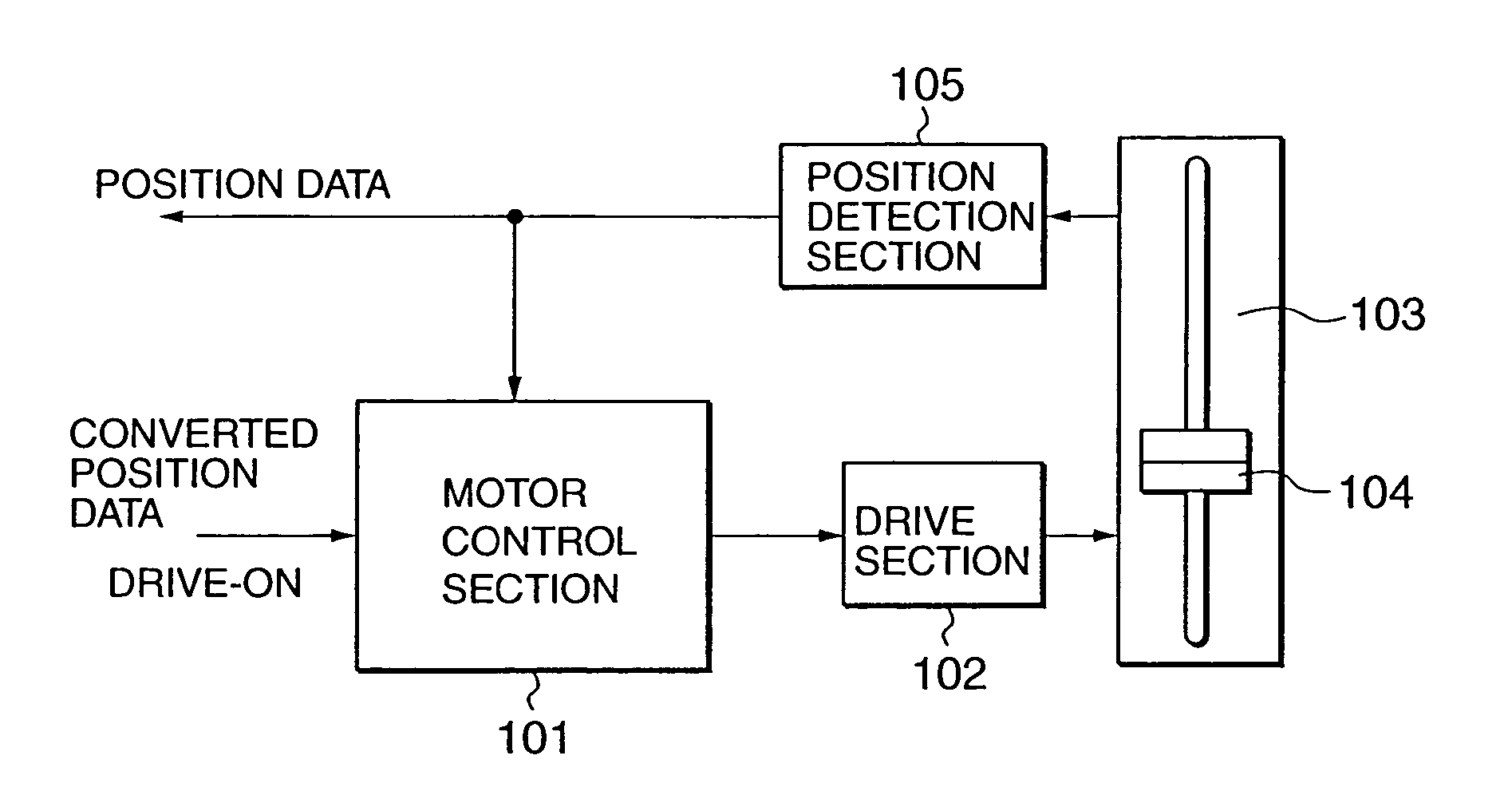
[0023]FIG. 1 shows a block configuration of an electric fader according to an embodiment of the present invention. The fader may be mounted in an operating panel of a system such as digital audio mixer for dealing with operation information of the audio mixer system. The electric fader comprises a motor control section 101, a drive section 102, a fader section 103 having a motor-driven sliding piece 104, and a position detection section 105. The position detection section 105 includes an analog / digital (A / D) converter and is designed to be capable of A / D conversion in an entire range in which fader sliding pieces can move. When the sliding piece 104 of the fader section 103 is operated manually, the position detection section 105 detects a voltage value or a current value that changes linearly in accordance with positions of the sliding piece 104. The posi...


PUM


Abstract

An operation apparatus is designed for use with a system to deal with operation information of the system. In the operation apparatus, an operation piece is manually operable to move in a linear or circular direction to a position indicative of the operation information. A detection section detects the position of the operation piece and outputs position data corresponding to the detected position. A drive section responds to position data inputted from the system to automatically move the operation piece to a position corresponding to the inputted position data. An acquiring section provisionally acquires a plurality of reference position data which are outputted from the detection section when the operation piece is placed at a plurality of reference positions such that the respective reference position data correspond to the respective reference positions. A correcting section corrects the position data outputted from the detection section according to the provisionally acquired reference position data and outputs the corrected position data to the system.

Description

BACKGROUND OF THE INVENTION[0001]1. Technical Field of the Invention[0002]The present invention relates to a fader position detection apparatus and a fader position control apparatus. More specifically, the present invention relates to a technology capable of accurately acquiring position data and moving a sliding piece of the fader to a target position despite a variance of accuracy of the electric fader's variable resistor and despite a variance of mounting positions of the faders on an operation panel.[0003]2. Prior Art[0004]Conventionally, an audio system such as a digital mixer often uses an operation panel containing an electric fader to set various parameter values (e.g., see patent document 1). The electric fader has a variable resistor that moves in interlock with a sliding piece. When the sliding piece is manually operated, its operated position is detected as a voltage value or a current value that varies with a resistance value of the variable resistor. An A / D converter ...

Claims


Application Information

Patent Timeline
IPC IPC(8): H04H7/00G05G19/00G05B11/36G05D3/12G05G23/00
CPCH04H60/04
Inventor AISO, MASARUKAGEYAMA, TAKAHISA
Owner YAMAHA CORP
Why Eureka
Try Eureka