Broadband waveform reconstruction for radar

a radar and waveform technology, applied in the field of radar technology, can solve the problems of increasing the pulse bandwidth, increasing the cost of producing the radar, and increasing the equipment expense, and achieve the effect of improving the resolution

Active Publication Date: 2005-11-22
HONEYWELL INT INC
View PDF11 Cites 2 Cited by
  • Summary
  • Abstract
  • Description
  • Claims
  • Application Information

AI Technical Summary

Benefits of technology

[0007]A method for reconstructing a large bandwidth signal from smaller bandwidth pulses over several transmit and receive cycles. Range resolution is greatly improved while keeping the bandwidth and attendant cost low.

Problems solved by technology

Generally, however, increasing pulse bandwidth requires greater equipment expense to effect the generation, transmission, reception, and resolution of increased pulse bandwidths.
One inherent expense in widening a bandwidth for a radar application is that antennae for the system must be designed to achieve an optimal waveform for a particular bandwidth, i.e. to control the selection of range resolution over side lobe-levels, to determine Doppler tolerance and resolution, etc.
What is needed in the art is a method of resolving radar returns of a pulse radar system to increase the range resolution without increasing the pulse bandwidth and thus the cost of producing the radar.

Method used


Image

  • Broadband waveform reconstruction for radar
  • Broadband waveform reconstruction for radar
  • Broadband waveform reconstruction for radar

Examples


Embodiment Construction

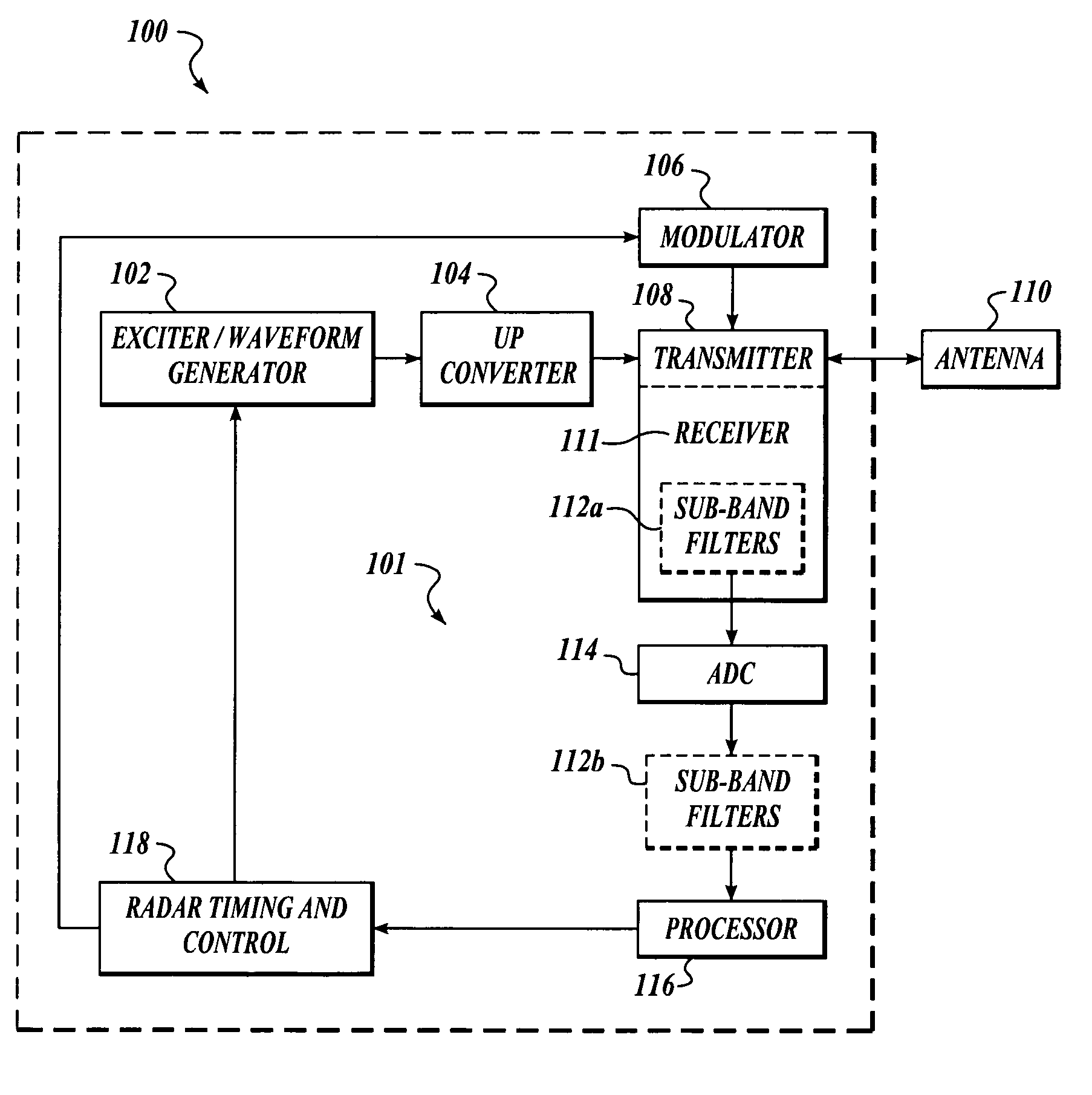
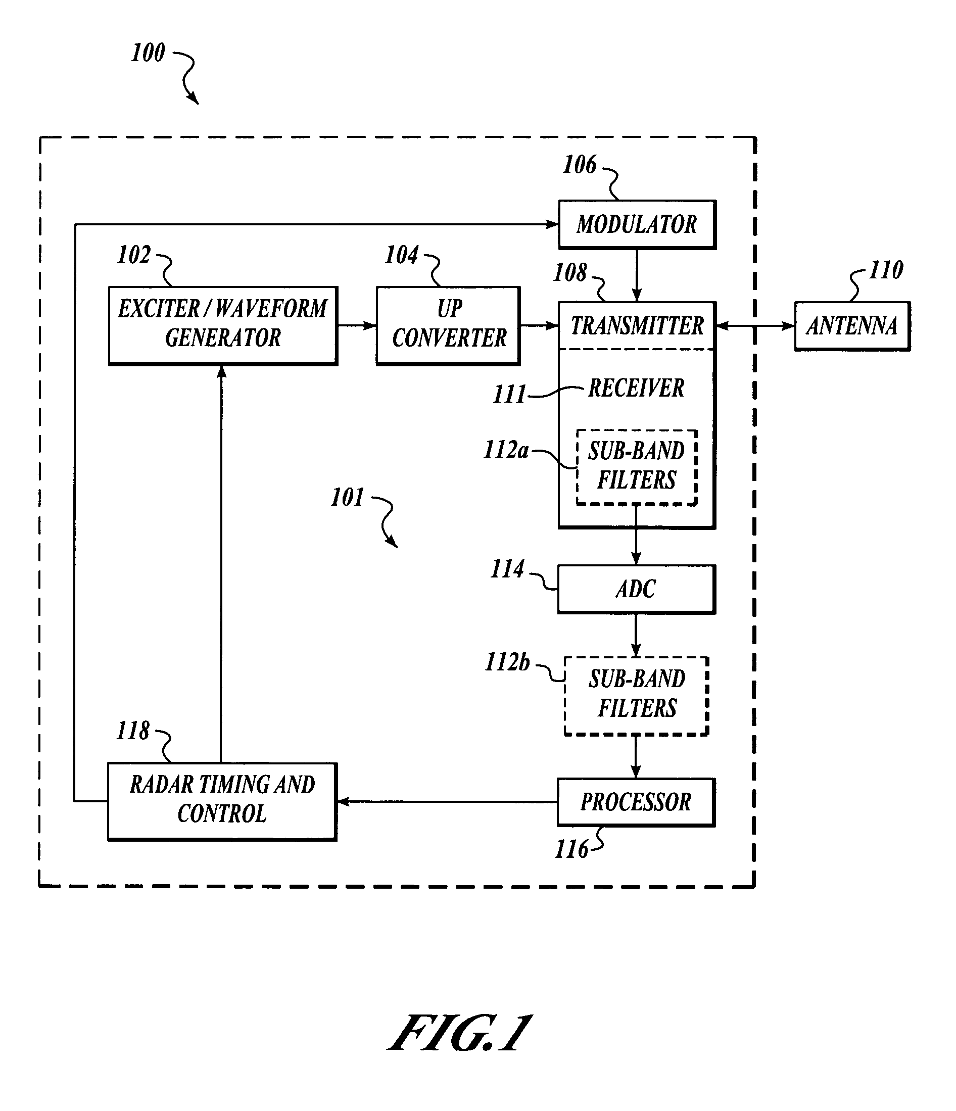
[0020]By way of overview, resolution of a radar operating within a bandwidth is improved by defining a quantity of substantially rectangular sub-band filters to subdivide the bandwidth in the frequency domain into the quantity of sequential sub-bands having a sub-bandwidth. Each signal sent by the radar is associated with a transmission temporal moment. Each of the quantity of return signals received is routed in one to one correspondence to the sub-band filters, each signal being received at a corresponding sub-band filter. The return signals received are summed by synchronizing the associated transmission temporal moment to produce a reconstructed return signal.

[0021]FIG. 1 is a generalized block diagram of a radar system 100 implemented in accordance with the teachings of the present invention. Those skilled in the art will appreciate that although the present teachings are disclosed with reference to an illustrative radar system implementation, the invention is not limited there...


PUM


Abstract

Resolution of a radar operating within a bandwidth is improved by defining a quantity of substantially rectangular sub-band filters to subdivide the bandwidth in the frequency domain into the quantity of sequential sub-bands having a sub-bandwidth. Each signal sent by the radar is associated with a transmission temporal moment. Each of the quantity of return signals received is routed in one to one correspondence to the sub-band filters, each signal being received at a corresponding sub-band filter. The return signals received are summed by synchronizing the associated transmission temporal moment to produce a reconstructed return signal.

Description

FIELD OF THE INVENTION[0001]This invention relates generally to radar technology and, more specifically, to radar return signal analysis.BACKGROUND OF THE INVENTION[0002]In a number of radar applications, features of interest in radar returns remain static for more than a single transmit and receive cycle. One such application is airborne ground mapping radar. One important metric in such applications is range resolution. Range resolution and cross-range resolution together determine the smallest sized ground objects or features that can be resolved by the radar. Range resolution in radar is proportional to signal (pulse) bandwidth, i.e. greater bandwidth allows better resolution. Generally, however, increasing pulse bandwidth requires greater equipment expense to effect the generation, transmission, reception, and resolution of increased pulse bandwidths.[0003]Most conventional radar systems operate in a relative narrow frequency band; they use harmonic (sinusoidal) signals as carr...

Claims


Application Information

Patent Timeline
Patent Type & Authority Patents(United States)
IPC IPC(8): G01S13/26G01S13/00G01S13/28
CPCG01S13/26G01S13/282
Inventor HOLMBERG, BART A.CHRISTIANSON, PAUL E.
Owner HONEYWELL INT INC
Why Eureka
Try Eureka