Small low profile antennas using high impedance surfaces and high permeability, high permittivity materials

a low-profile, high-permittivity material technology, applied in the field of antennas, can solve the problems of significant fraction of surface wave energy dissipation, associated narrow bandwidth of approximately 8%, and suffer from drawbacks

Inactive Publication Date: 2005-11-22
ARMY US SEC THE THE
View PDF8 Cites 48 Cited by
  • Summary
  • Abstract
  • Description
  • Claims
  • Application Information

AI Technical Summary

Benefits of technology

[0009]In accordance with an embodiment of the present invention, a low profile antenna comprises an antenna and a ground plane structure operatively associated with the antenna. The ground plane structure comprises a generally planar surface, at least one protrusion

Problems solved by technology

The antenna, described by How et al, suffers from the drawback that a significant fraction of energy is dissipated in surface waves because of the limited size of the ground plane.
One disadvantage that arises in connection with an

Method used


Image

  • Small low profile antennas using high impedance surfaces and high permeability, high permittivity materials
  • Small low profile antennas using high impedance surfaces and high permeability, high permittivity materials
  • Small low profile antennas using high impedance surfaces and high permeability, high permittivity materials

Examples


Embodiment Construction

[0014]One embodiment of the present invention concerns a low profile antenna that is both efficient and that is capable of transmitting a signal with an increased bandwidth. The low profile antenna comprises an antenna and a high impedance ground plane structure that functions to reduce surface waves while not compromising bandwidth. Also, the low profile antenna may be configured for use at relatively low microwave frequencies without incurring unsuitably large dimensional requirements.

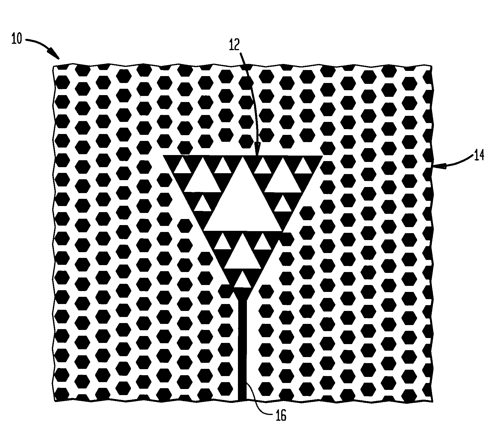
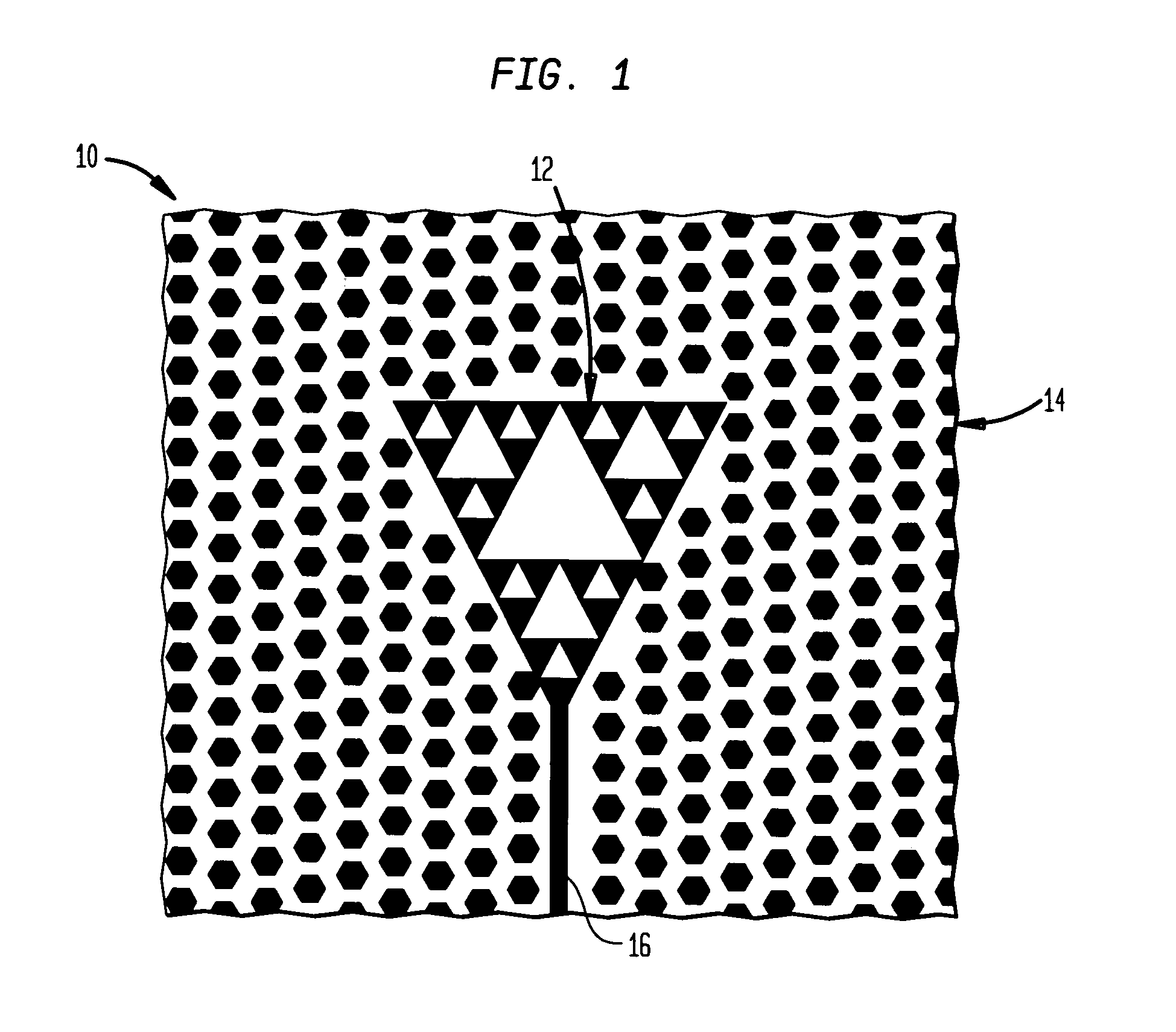
[0015]Referring now to FIG. 1, a low profile antenna in accordance with one embodiment of the present invention is illustrated generally at 10. In this embodiment, the low profile antenna 10 comprises an antenna 12 and a ground plane structure 14.

[0016]The antenna 12 preferably comprises a known fractal, microstrip antenna, although, it will be understood that any suitably low profile antenna may be employed in the practice of the present invention. The antenna 12 is illustrated as having a generally...


PUM


Abstract

A low profile antenna includes an antenna and a ground plane structure operatively associated with the antenna. The ground plane structure has a generally planar surface, at least one protrusion extending from the planar surface and a dielectric substrate supported by the planar surface. The dielectric substrate includes a relative permeability (μ) of greater than or equal to about one and a relative permittivity (ε) of greater than or equal to about one.

Description

GOVERNMENT INTEREST[0001]The invention described herein may be manufactured, used, imported, sold, and licensed by or for the Government of the United States of America without the payment of any royalty thereon or therefor.BACKGROUND OF THE INVENTION[0002]1. Field of the Invention[0003]The present invention relates generally to antennas and, more particularly, to antennas which have a low profile.[0004]2. Related Art[0005]Low profile antennas are known. For example, U.S. Pat. No. 5,327,148 to How et al describes a microstrip antenna that has a substrate that includes a ground plane conductor disposed over a first surface and a strip conductor disposed over a second surface. A DC magnetic field biasing circuit provides a directed DC magnetic field to the substrate such that the strip conductor radiates electromagnetic energy that has a circular polarization. In one particular embodiment, the substrate is composed of magnesium ferrite and in another, a second substrate of ferrite mat...

Claims


Application Information

Patent Timeline
IPC IPC(8): H01Q1/38H01Q1/36H01Q9/40H01Q15/00
CPCH01Q1/36H01Q9/40H01Q15/008H01Q15/0093
Inventor CADOTTE, JR., ROLANDWILBER, WILLIAM D.
Owner ARMY US SEC THE THE
Why Eureka
Try Eureka