
Method for constructing service providing system

a technology of a service provider and a system is applied in the field of constructing a service provider system, which can solve the problems of inability to ensure the reusability and change facility of software, and the software architecture is likely to be unstable, so as to achieve the effect of easy adjustment, easy adjustment, and easy adjustmen

Inactive Publication Date: 2005-11-22
KK TOSHIBA
View PDF6 Cites 2 Cited by
  • Summary
  • Abstract
  • Description
  • Claims
  • Application Information

AI Technical Summary

Benefits of technology

[0009]It is therefore an object of the present invention to eliminate the aforementioned problems and to provide a method for constructing a service providing system, such as a monitoring system; a service providing system; and a computer readable recording medium in which a program for service providing system or a framework for service providing system has been recorded, the method, system and program being capable of improving the stability of the architecture of a software against specification change and extension and of improving the reusability and change facility of the software.
[0021]Thus, according to the present invention, since a service providing system is constructed using a framework for service providing system which uniformly expresses the construction of a service providing system and services, it is possible to improve the stability of the architecture of a software against specification change and extension, and it is possible to improve the reusability and change facility of the software, so that it is possible to efficiently develop the service providing system.
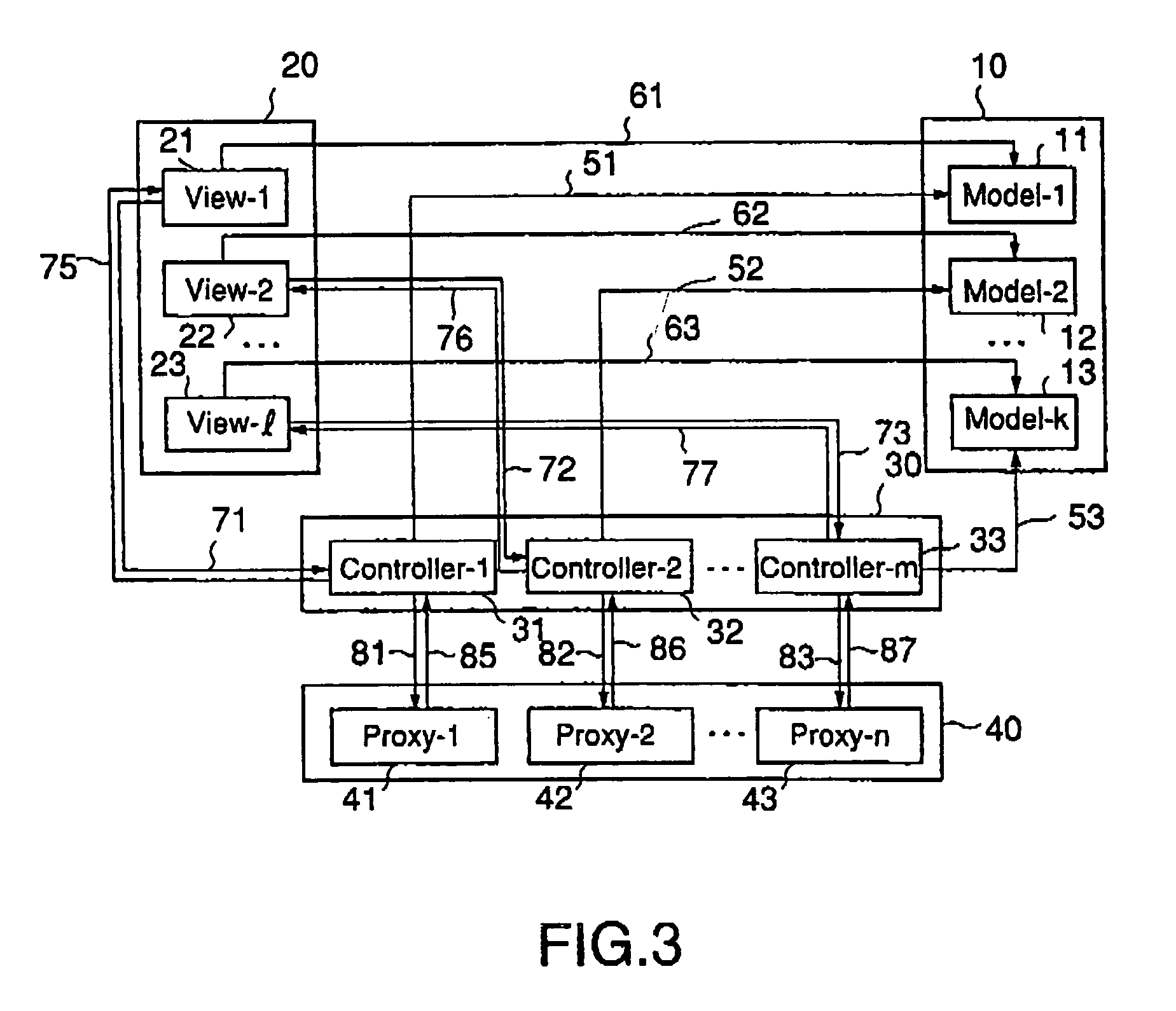
[0022]In addition, according to the present invention, in the service providing system, the integrated control part controls data which are held in the data holding part, and connects the data holding part with the user interface part to provide various services for the object system on the basis of data which are given from the user or the object system, so that it is possible to reduce the mutual-dependence relation of the respective parts in the monitoring system to localize the modified range in accordance with specification change and extension.
[0024]In addition, according to the present invention, the class of each of the data holding part, the object system interface part and the integrated control part is prepared every kind of object systems, and the class of the user interface part is prepared every kind of screens for interface, so that it is possible to easily cope with the addition and deletion of the object systems and screens for interface. In addition, if the class of the data holding part is prepared every kind of data, which are used in object systems, in addition to the kind of the object systems, and if the class of the integrated control part is prepared every kind of services, which are provided for object systems, in addition to the kind of the object systems, it is possible to easily cope with the addition and deletion of data and services. Moreover, if the class of the integrated control part is divided into an upper class, which is prepared every kind of object systems, and a lower class which is prepared every kind of services which are provided for the object systems under the upper class, it is possible to easily cope with the addition and deletion of services for the same object system.

Problems solved by technology

However, any reference models for uniformly expressing the configuration of monitoring systems and service are not conventionally established, so that there are problems in that if specification change or extension is carried out, the architecture of the software is likely to be unstable, and the reusability and change facility of the software can not easily be ensured.

Method used


Image

  • Method for constructing service providing system
  • Method for constructing service providing system
  • Method for constructing service providing system

Examples


first preferred embodiment

[0083]Referring to FIGS. 6 through 10, the first preferred embodiment of a monitoring system according to the present invention will be described below. Furthermore, in this first preferred embodiment, it is supposed that the number of external apparatuses serving as objects to be monitored is one, only one kind of data (setting data) exist as internal data used in the external apparatus, and only a setting screen exists as a CUI screen for displaying the data.

[0084]FIG. 6 shows a class structure of the first preferred embodiment of a monitoring system according to the present invention.

[0085]As shown in FIG. 6, in the monitoring system according to the first preferred embodiment, each of the model part 10, the view part 20, the controller part 30 and the proxy part 40 include a single class. That is, the model part 10 includes a Model-1 class 11 for holding setting data which are used in an external apparatus serving as an object to be monitored. In addition, the view part 20 inclu...

second preferred embodiment

[0097]Referring to FIGS. 11 through 16, the second preferred embodiment of a monitoring system according to the present invention will be described below. In this second preferred embodiment, a build-up service for an external apparatus is added to the setting service for the external apparatus in the above described first preferred embodiment, and other basic constructions and operations are substantially the same as those in the above described first preferred embodiment. In the second preferred embodiment, the same reference numbers are given to the same portions as those in the first preferred embodiment, and the detailed description thereof is omitted.

[0098]FIG. 11 shows a class structure of the second preferred embodiment of a monitoring system according to the present invention.

[0099]As shown in FIG. 11, in the monitoring system according to the second preferred embodiment, the controller part 30 includes a Controller-2 class 32 and a Controller-3 class 33 (lower classes) in ...

third preferred embodiment

[0112]Referring to FIGS. 17 through 21, the third preferred embodiment of a monitoring system according to the present invention will be described below. In this third preferred embodiment, status data are added as internal data to the setting data in the above described first preferred embodiment, and a status displaying screen is added to the setting screen in the above described first preferred embodiment as the GUI screen for displaying these data. Other basic constructions and operations are substantially the same as those in the above described first preferred embodiment. In the third preferred embodiment, the same reference numbers are given to the same portions as those in the first preferred embodiment, and the detailed description thereof is omitted.

[0113]FIG. 17 shows a class structure of the third preferred embodiment of a monitoring system according to the present invention.

[0114]As shown in FIG. 17, in the monitoring system according to the third preferred embodiment, ...


PUM


Abstract

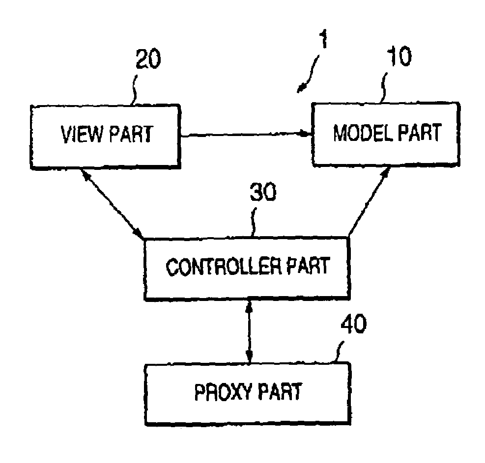
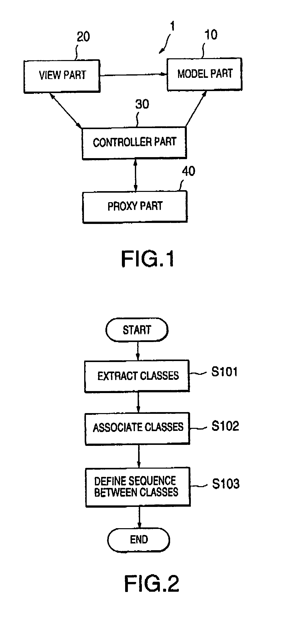
A monitoring system is constructed using a framework 1 described by an object-oriented language. The framework 1 includes a model part 10 for holding data relating to an external apparatus serving as an object to be monitored, a view part 20 provided between the monitoring system and a user, a proxy part 40 for exchanging data between the monitoring system and the external apparatus in accordance with a predetermined protocol, and a controller part 30. The controller part 30 controls data of the model part 10, and connects the model part 10 with the view part 20 to provide various services for the external apparatus on the basis of data which are given from the user or the external apparatus. The proxy part 40 converts communication data into a format of internal data which is handled in the monitoring system. Thus, it is possible to provide a service providing system capable of improving the stability of the architecture of a software against specification change and extension, and of improving the reusability and change facility of the software.

Description

BACKGROUND OF THE INVENTION[0001]1. Field of the Invention[0002]The present invention relates generally to a method for constructing a service providing system, such as a system for monitoring an external apparatus. More specifically, the invention relates to a method for constructing a serving providing system using a framework for service providing system, which is described by an object-oriented language or the like; a service providing system constructed by the method; and a computer readable recording media in which a program for service providing system or a framework for service providing system has been recorded.[0003]2. Description of the Related Art[0004]As a service providing system for providing service for an object system, there is known a monitoring system for exchanging monitoring instructions and monitored results with an external apparatus (an object system) serving as a service provided object to provide various services, such as the setting of initial data, build...

Claims


Application Information

Patent Timeline
Patent Type & Authority Patents(United States)
IPC IPC(8): G06F9/44
CPCG06F8/20
Inventor HAYASE, TAKEO
Owner KK TOSHIBA
Learn More