
Integral compressor housing of gas turbine engines

a gas turbine engine and compressor housing technology, applied in the direction of engine starters, turbine/propulsion engine ignition, combustion air/fuel air treatment, etc., can solve the problems of difficult to predict structural behavior, inability to hold tighter clearance between components, and multiple component approaches that do not meet the light weight requirements of high-performance aircraft engines

Inactive Publication Date: 2005-11-29
HONEYWELL INT INC
View PDF16 Cites 18 Cited by
  • Summary
  • Abstract
  • Description
  • Claims
  • Application Information

AI Technical Summary

Benefits of technology

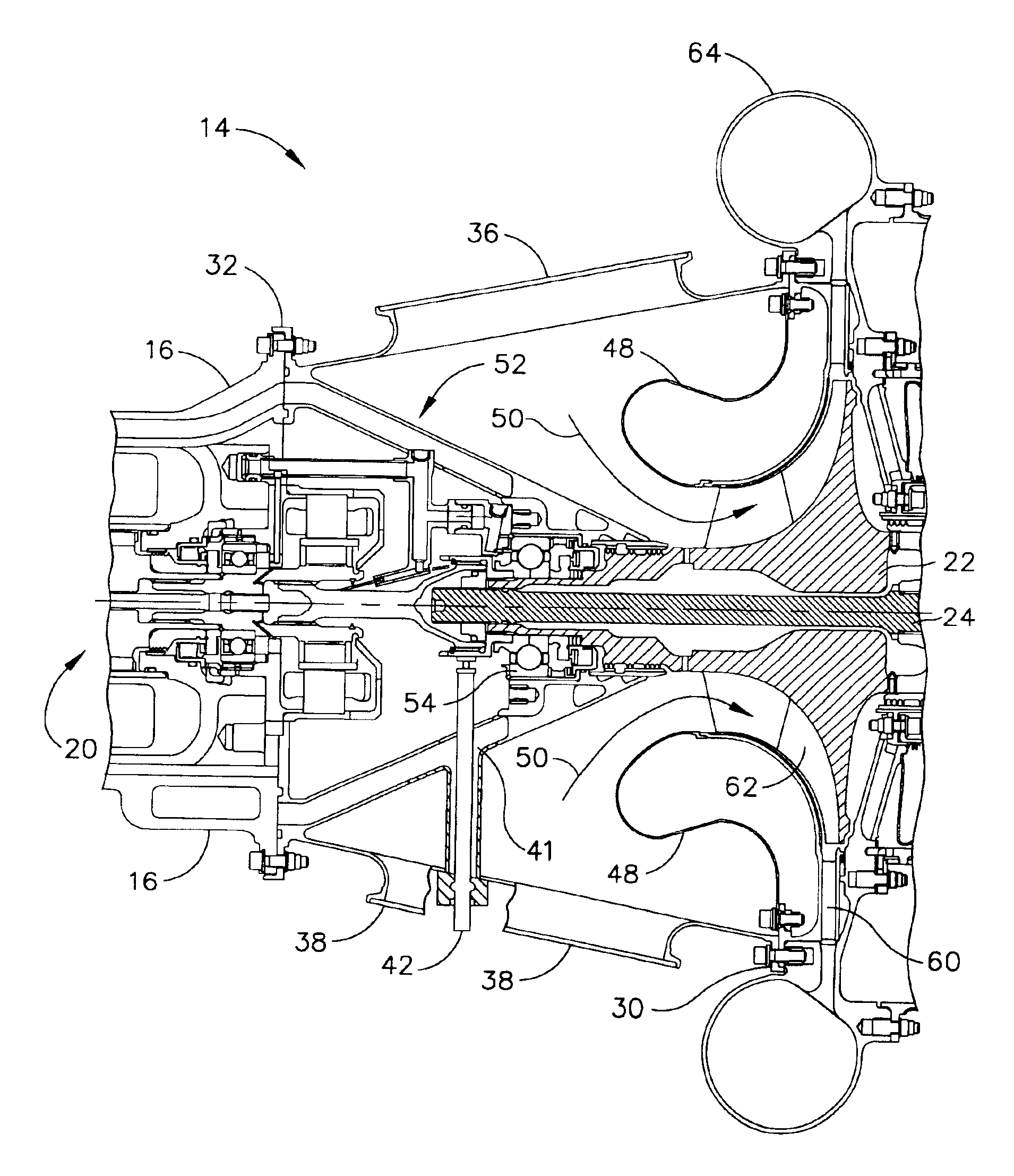
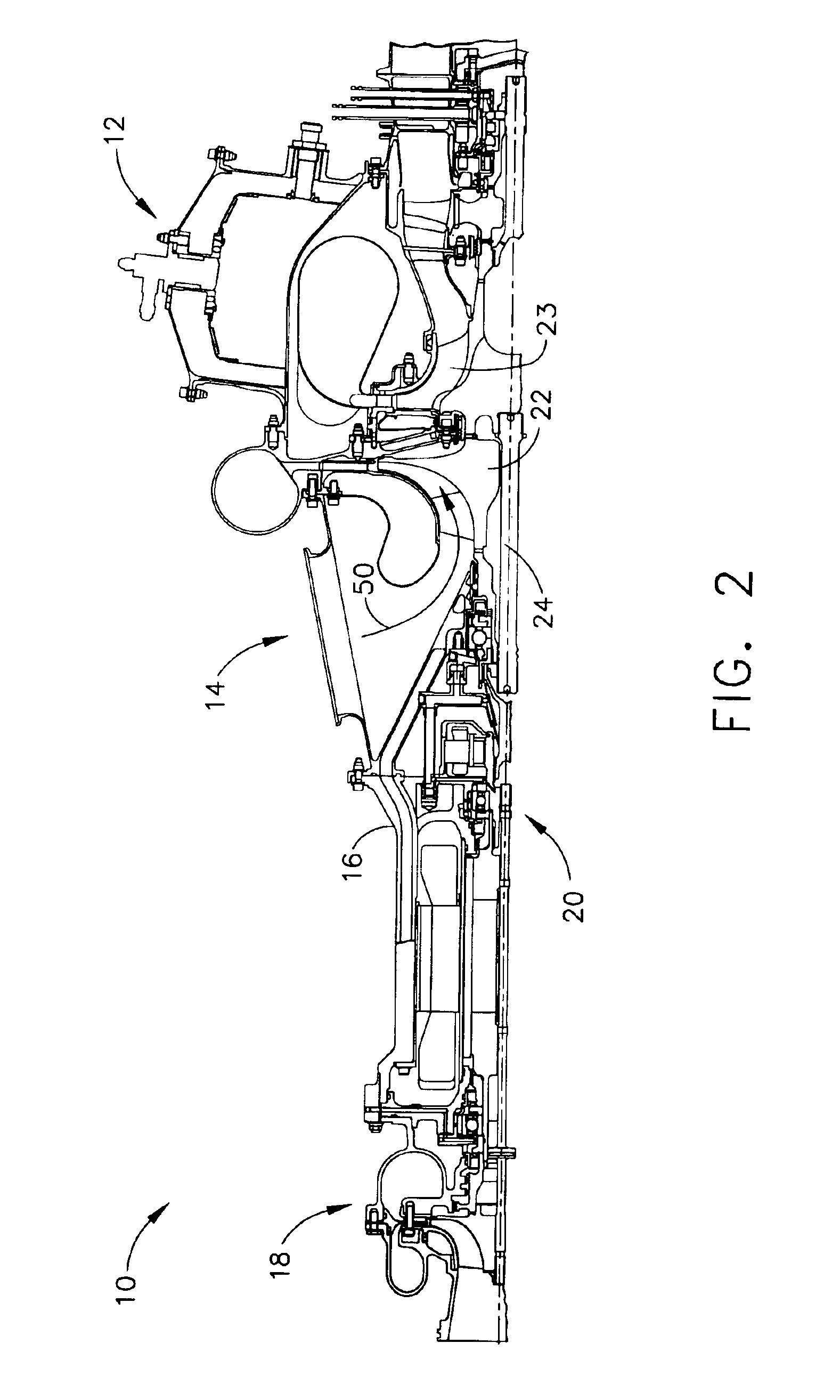
The present invention provides a compressor module for a gas turbine engine that includes an external housing with multiple inlets, a forward bearing housing conically extending from the forward end of the external housing, and a bell mouth circumferentially disposed within the external housing. The compressor module also includes a compressor wheel rotatably disposed at the aft end of the external housing, a compressor shroud / diffuser, a speed sensor, and a generator within the generator housing. The compressor module provides an air path for air to flow to the rotatable compressor wheel and to be discharged into a compressor discharge scroll at an increased pressure from a pressure at the inlet duct. The invention also provides a method of providing auxiliary power with a gas turbine engine by attaching a generator housing to the forward end of the external housing, providing a compressor module with the necessary components, and rotating the shaft to provide mechanical rotational power to the generator. The technical effects of the invention include increased efficiency and power output of the gas turbine engine, as well as improved speed and reliability of the auxiliary power system.

Problems solved by technology

A multiple component system makes it difficult to predict the structural behaviors due to thermal and mechanical loading during transient conditions.
Holding tighter clearances between components becomes impossible due to the manufacturing tolerance build up among the various components.
Such a multiple component approach will not meet the light weight requirements of high-performance aircraft engines, such as typical fighter jet engines.
The power and thermal management system (PTMS) of high-performance aircraft has technical challenges that require a novel approach in the design of the compressor module.

Method used


Image

  • Integral compressor housing of gas turbine engines
  • Integral compressor housing of gas turbine engines
  • Integral compressor housing of gas turbine engines

Examples


Embodiment Construction

[0018]The following detailed description is of the best currently contemplated modes of carrying out the invention. The description is not to be taken in a limiting sense, but is made merely for the purpose of illustrating the general principles of the invention.

[0019]Broadly, the present invention provides for a compressor of a gas engine, such as a gas turbine engine, having the number of components reduced, as described below, by at least one component and up to four components. Such a design allows for a reduction in weight. A reduced number of components allows the components to be arranged in close tolerance. In conventional compressor designs, the components may vary in material and, thus, vary in heat capacities. Such variation requires additional component tolerances because one material may thermally expand differently as compared to another component. Further, manufacturing variances between the components require additional component tolerances in order to account for th...


PUM


Abstract

A turbine engine compressor design utilizing multiple component integration, thereby reducing the number of required engine components. In conventional compressor designs, a multiple component system makes it difficult to predict the structural behaviors due to thermal and mechanical loading during transient conditions. The compressor design of the present invention has three main parts: a forward bearing housing, a bell-mouth (heat shield) and a coupled impeller shroud / diffuser. Such a design achieves the design objectives of the present invention, including reducing weight, reducing cost, minimizing tolerance build up and improving aerodynamic performance by utilizing multiple component integration for multiple modes of engine operation.

Description

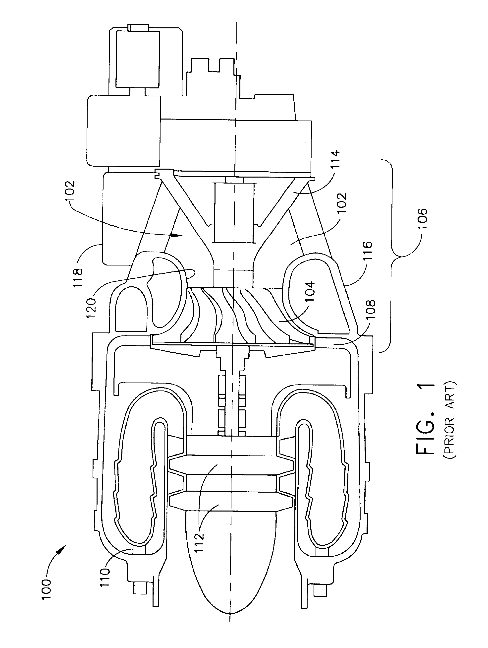
[0001]This invention was made with Government support under contract number N00019-01-C-3002 with outside funding from Lockheed Martin—U.S. government under the Joint Strike Fighter (JSF) program. The Government has certain rights in this inventionBACKGROUND OF THE INVENTION[0002]The present invention generally relates an engine compressor and, more specifically, to a turbine engine compressor utilizing multiple component integration, thereby reducing the number of required engine components.[0003]Referring to FIG. 1, there is shown a conventional small gas turbine engine 100. Intake air is taken into engine 100 as shown by arrows 102. The intake air passes through a compressor wheel 104. As air passes through the compressor section 106, it is accelerated outwards at high speeds. The accelerated air is slowed down in a diffuser 108, which comprises a ring of static vanes. A portion of the accelerated air may be used in a combustion chamber 110, and a portion of the accelerated air m...

Claims


Application Information

Patent Timeline
Patent Type & Authority Patents(United States)
IPC IPC(8): F02C6/08F02C7/00F02C7/04F02C7/26
CPCF02C7/06F02C7/20F04D29/4206Y02T50/672F05D2230/52Y02T50/60
Inventor NGUYEN, LY D.FROST, CRISTOPHERMATY, RONALD P.WAIT, JOHN M.SMOKE, JASON C.WHEELER, LORI M.KOCHER, RICHARD D.
Owner HONEYWELL INT INC
Learn More