Rain sensor mounting system

a technology for mounting systems and sensors, applied in the field of rearview assemblies of vehicles, can solve the problems of affecting the appearance and styling of vehicles, affecting the stability of the vehicle, and affecting the operation of the vehicle, so as to achieve the effect of greater flexibility and greater range of motion of the mirror assembly housing

Inactive Publication Date: 2005-11-29
DONNELLY CORP
View PDF14 Cites 389 Cited by
  • Summary
  • Abstract
  • Description
  • Claims
  • Application Information

AI Technical Summary

Benefits of technology

[0018]According to yet another aspect of the invention, a rearview mirror assembly is disclosed which includes a rearview mirror housing having a reflective element supported therein, a support arm mounted to the rearview mirror housing that terminates in a button attaching mirror mount, and a rain sensor module. The rain sensor module includes a rain sensor module housing having a first side or end and a second side or end, with the second side preferably including a port. The second side is positioned adjacent an inner surface of the vehicle windshield and is adapted to mount the rain sensor module housing to the vehicle windshield. The rain sensor module housing preferably also includes a cover, which covers an access opening provide in the rain sensor module housing and a rain sensor which is supported in the rain sensor module housing. Alternately, the rain sensor module may be a unitary member or construction wherein the rain sensor is housed, preferably resiliently housed, within the cavity of the housing such that the detecting surface of the rain sensor is positioned, and preferably urged to protrude, at the second side (end) of the housing that is opposite and opposing the first side (end). The rain sensor includes a detector surface, which preferably is extended though a port provided in the housing for optically coupling the rain sensor to the inner surface of the vehicle windshield. A mirror mount extends from the housing, for securing the support arm to the housing. Furthermore, the rain sensor module housing includes a biasing member supported therein which is interposed between a portion of the rain sensor module housing and the rain sensor for urging the detecting surface of the rain sensor to optically couple the rain sensor to the vehicle windshield for detecting moisture on an outer surface of the vehicle windshield. The rain sensor module can be provided in a variety of constructions, thus providing economic, convenience and flexibility benefits to automakers and their suppliers. For example, the housing of the rain sensor module and the mirror mount extending therefrom can be a unitary construction (such as can be formed by mechanically attaching or adhesively attaching a mirror mounting button to an already formed housing, or by attaching the mirror mounting button to the housing while the housing itself is being formed, such as by integral molding as is known in the molding arts), or the rain sensor, housing and mirror mount can be provided as a unitary construction, such as a unitary rain sensor module.
[0020]As will be understood, the rain sensor mount of the present invention provides numerous advantages over prior known rain sensor mounting arrangements. For example, the rain sensor module can be attached by the windshield manufacturer at the time of the windshield fabrication and shipped to the automobile assembly plant where the rearview mirror assembly can be attached to the rain sensor module. Alternatively, the annular member may be attached to the windshield by the windshield manufacturer at the time of fabrication leaving the installation of the rain sensor module assembly optional. For example, windshields with the rain sensor mount pre-attached can be received at the vehicle assembly plant, and the rain sensor module can be attached, and the rearview mirror assembly also attached to the module, as the vehicle passes along the vehicle assembly line. Furthermore, the rain sensor mount can be mounted without detracting from the styling of the vehicle and, moreover, without obstructing the view of the driver of the vehicle. In addition, the rain sensor mount can be adapted to support a wide range of rearview mirror assemblies and, notably, rearview mirror assemblies with double ball joint support arms to permit a greater range of motion of the mirror assembly housing than the present rains sensor mounts permit. Thus, the present rain sensor mount affords the automobile manufacturer greater flexibility in its selection of the mirror assembly and the button mount and therefore can accommodate most markets' regulations.

Problems solved by technology

Optical adhesives are difficult and expensive to remove during service replacement of a damaged windshield.
Furthermore, the optical adhesives, which are used to attach the rain sensors to the inner surface of the windshield, may be visible from the outside of the vehicle and, thus, can potentially detract from the vehicle appearance and styling.
Moreover, the attachment of the rain sensor to the windshield either by bonding with an adhesive or by mechanical attachment often creates a noticeable obstruction of the forward field of view due to the separate and, frequently, bulky housing provided for the rain sensor unit.
Furthermore, the location and bulky size of the rain sensor unit may further increase the risk of potential injury of the vehicle occupants should they impact the windshield in an accident.
When these mounting buttons are attached to the windshield, the manufacturer may need to attach a second structure, such as a mechanical guide or rail to which the rain sensor is then later attached to the vehicle, which would ultimately increase the cost of the windshield.
Although the aforementioned construction has several advantages, it has numerous disadvantages that can limit its widespread application in vehicles.
Furthermore, this construction requires that the articulation of the mirror housing about the support arm be limited to a single point at the juncture of the support arm to the housing.
Therefore, the present design is limited for use on single pivot mirror supports and is unsuitable for dual pivot mounting supports, which are commonly used on a wide variety of vehicles.
It is also necessary to stock a special mirror design when a rain sensor is desired, which adds to inventory requirements.
Therefore, double ball joint mirrors would appear to not be well suited to accommodate a rain sensor unit within the support arm cavity.
The presence of the rain sensor in the support arm increases the weight of the rearview mirror assembly.
With increased weight, potential exists for detrimental effects on the mirror assembly vibration performance.
Furthermore, placement of the rain sensor in the support arm limits the choice of rearview mirror suppliers since only a limited number of mirror assembly support arm designs can accommodate such mounting of the rain sensor.
With the design illustrated in FIGS. 7-9, the choice of the mirror button design is, therefore, also limited, thus placing potential limitation on the use of these rain sensor mounts in certain countries.

Method used


Image

  • Rain sensor mounting system
  • Rain sensor mounting system
  • Rain sensor mounting system

Examples


Embodiment Construction

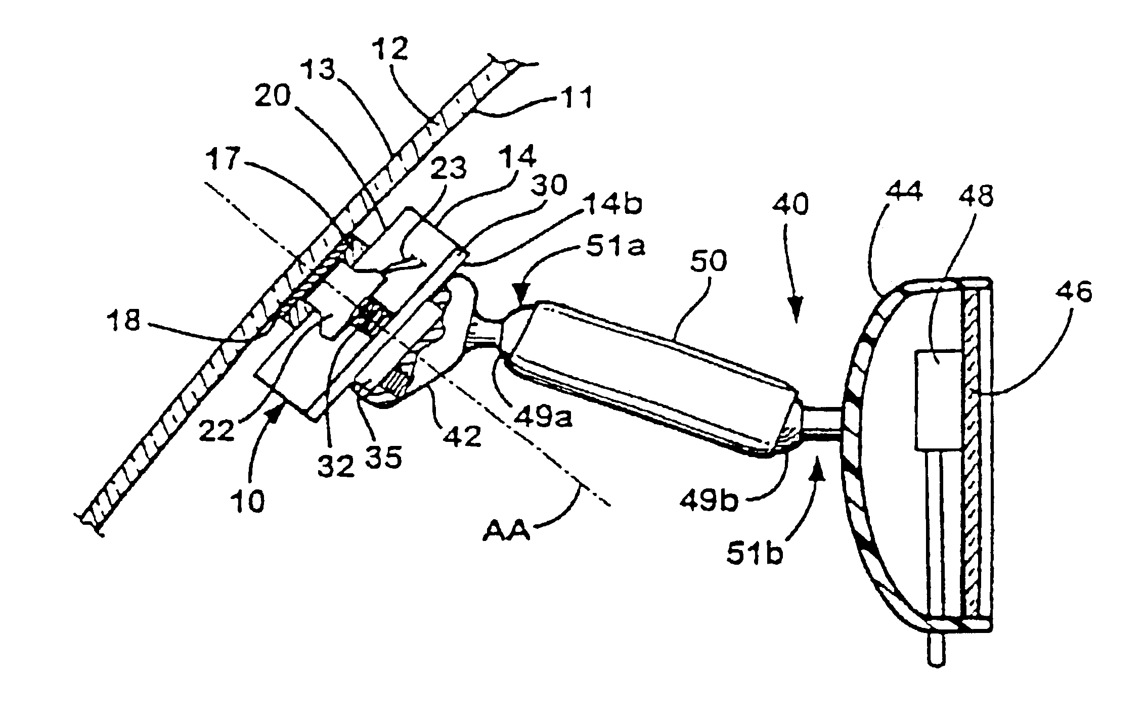
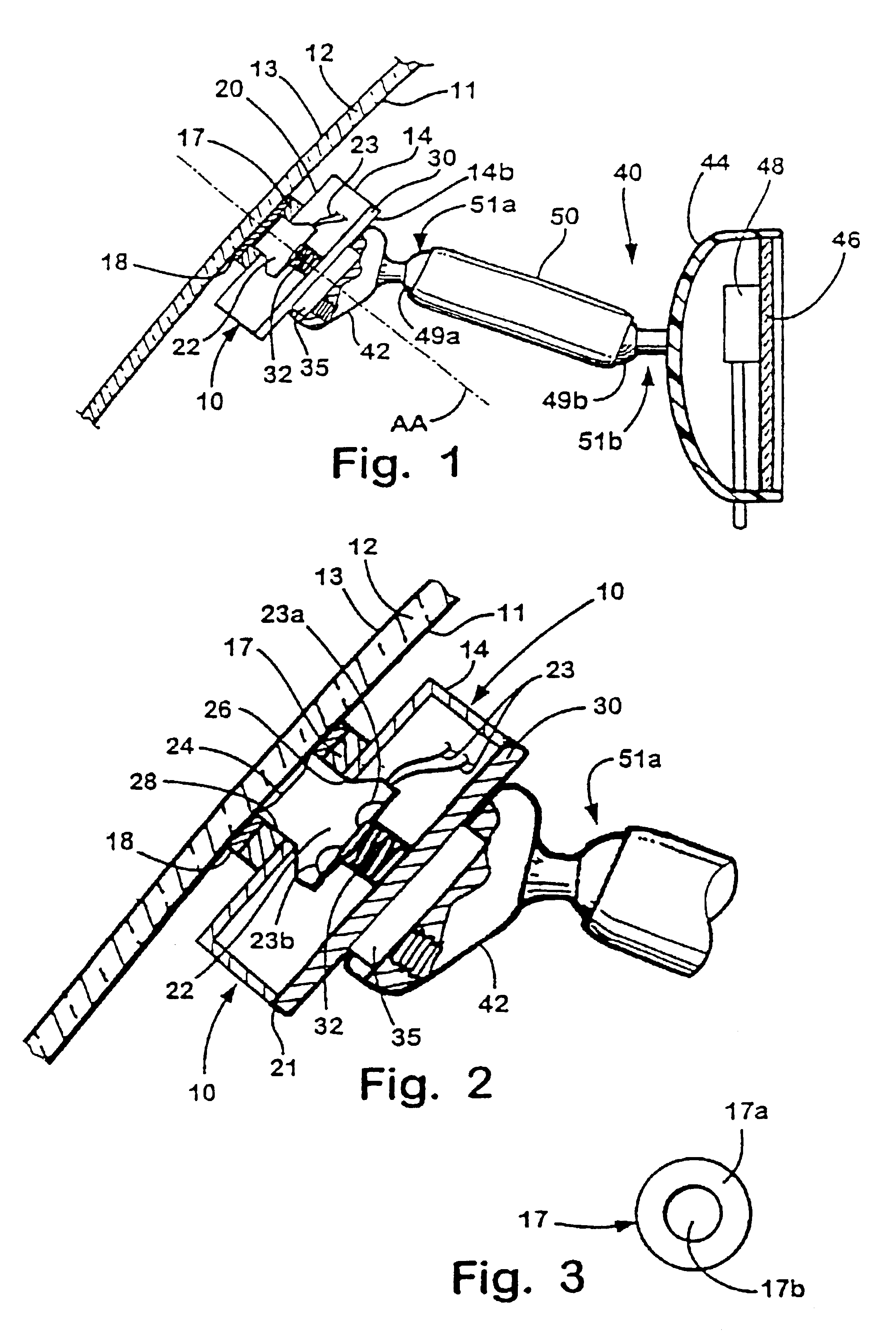
[0032]Referring to FIGS. 1 and 2, a rain sensor module assembly 10 of the present invention is shown mounted to the inner surface 11 of a windshield 12. Rain sensor module assembly 10 is positioned on inner surface 11 of windshield 12 for detecting moisture, such as rain droplets, on the outer surface 13 and, optionally, on inner surface 11 of windshield 12, as will be more fully explained below.

[0033]Rain sensor module assembly 10 is mounted to inner surface 11 of windshield 12 by a rain sensor mounting button 17. Rain sensor mounting button 17 is preferably adhered to inner surface 11 of windshield 12 by a layer 18 of adhesive such as an epoxy, a polyvinyl butyral, a urethane, or a silicone adhesive material or the like. In the illustrated embodiment rain sensor mounting button 17 is circular in shape having a solid annular outer portion 17a and inner hollow open central portion 17b. Solid portion 17a of rain sensor mounting button 17 may comprise a polymer material, such as an en...


PUM


Abstract

A vehicular rain sensor mounting system comprises a module assembly adapted for attachment to an attachment member on the inner surface of a vehicle windshield. The module assembly comprises a first side configured to be generally adjacent the inner surface of the vehicle windshield and a second side generally opposing the first side. A rearview mirror assembly mounting member is provided at the second side. The system further comprises a rearview mirror assembly having a mirror mount adapted for attachment to the rearview mirror assembly mounting member provided at the second side of the module assembly. The module assembly includes a rain sensor having a detecting surface. The detecting surface of the rain sensor contacts the inner surface of the windshield when the module assembly is attached to the attachment member on the inner surface of the vehicle windshield.

Description

[0001]This application is a continuation application under of application Ser. No. 10 / 023,162, filed Dec. 17, 2001 now U.S. Pat. No. 6,516,664, by Niall R. Lynam, entitled, RAIN SENSOR MOUNT FOR USE IN A VEHICLE, which is a continuation application of U.S. pat. application Ser. No. 09 / 860,361, filed May 18, 2001, now U.S. Pat. No. 6,341,523, which is a continuation application of U.S. pat. application Ser. No. 09 / 003,966, filed on Jan. 7, 1998, now U.S. Pat. No. 6,250,148, which are incorporated by reference herein in their entireties.TECHNICAL FIELD AND BACKGROUND OF THE INVENTION[0002]This invention relates to a vehicular rearview assembly. More particularly, the present invention relates to mounting of a rain sensor within a rearview mirror assembly support.[0003]Rain sensors for detecting moisture due to rain, road splash, and the like on the outside of a vehicular windshield are conventionally mounted to the inner cabin surface of the vehicle windshield. Rain sensors typically ...

Claims


Application Information

Patent Timeline
Patent Type & Authority Patents(United States)
IPC IPC(8): B60R1/04B60R1/12B60R11/00B60R11/02B60S1/08G02B6/00G02B27/00G06Q20/00
CPCB60R1/04B60R1/12B60R11/0247B60S1/0822B60S1/0885B60R11/0241B60R2001/1223B60R2011/0026B60R2011/0033B60S1/0833B60S1/0881G02B6/00G02B2027/0118G02B2027/012
Inventor LYNAM, NIALL R.
Owner DONNELLY CORP
Why Eureka
Try Eureka