Adjustable movable IV stand

a movable, adjustable technology, applied in the field of iv poles, can solve the problems of not having a handle, not always comfortably or safely grasping the iv pole with sufficient firmness or stability, and prior mobile iv poles generally lack a handl

Active Publication Date: 2005-11-29
SAFEPOLE
View PDF12 Cites 56 Cited by
  • Summary
  • Abstract
  • Description
  • Claims
  • Application Information

AI Technical Summary

Benefits of technology

[0009]The present invention relates to an IV pole which overcomes one or more of the foregoing drawbacks of prior IV poles.

Problems solved by technology

Early mobile IV poles, however, have suffered from a number of drawbacks.
For example, prior mobile IV poles generally have not had a handle which could easily be adjusted upwardly or downwardly by a patient to accommodate patients of different heights.
Prior handles also generally have been oriented horizontally such that patients could not always comfortably or safely grasp the IV pole with sufficient firmness or stability to move the IV pole while walking.
Prior mobile IV poles also typically have had exposed wheels, and many hospital patients have injured themselves by accidentally kicking or tripping over those exposed wheels while walking alongside such prior IV poles.
Several additional problems have arisen because IV poles are commonly used to carry medication pumps and other electrical equipment alongside a patient.
However, these power cords often become entangled or caught on other objects while the IV pole is being moved or while the patient is moving near the IV pole.
This, in turn, has, in some cases, caused patients to trip and fall, or IV poles to topple, possibly resulting in injury and pain to the patient or in hazardous interruption of the patient's transfusion either because the flexible tubing is excessively strained and IV needles are pulled out of the patient, or because the power cords become unplugged from the electrical equipment and / or from the wall outlet.
Further, while newer medication pumps and other electrical equipment may have internal batteries which allow the pumps or equipment to operate for some time while unplugged, the batteries in many such devices do not provide battery-powered operation for very long.
A further problem with such IV poles is that the hooks have been oriented in different directions such that the medication bags hung from such IV poles correspondingly are oriented in different directions.
As a result, it becomes more difficult for a health care provider to view the medication bag labels which identify the contents of the medication bags, particularly for patients requiring a large number of contemporaneous transfusions.
In addition, the lengths of flexible tubing extending from multiple medication bags hanging on an IV pole often have become crossed or entangled with one another, which also has made it more burdensome for heath care providers to distinguish one length of flexible tubing from another when connecting the tubing to the medication bags and to the patient and / or when injecting additional medications into the patient via inlets in the flexible tubing.
Medication bags often had to be suspended from the hooks of prior IV poles using extension hooks or other apparatus, which is cumbersome for healthcare providers and creates risk of error in the administration of various intravenous medications.
Prior IV poles have not provided adequate means for supporting a catheter bag at a vertical position below the pelvis of the patient to ensure proper operation.

Method used


Image

  • Adjustable movable IV stand
  • Adjustable movable IV stand
  • Adjustable movable IV stand

Examples


Embodiment Construction

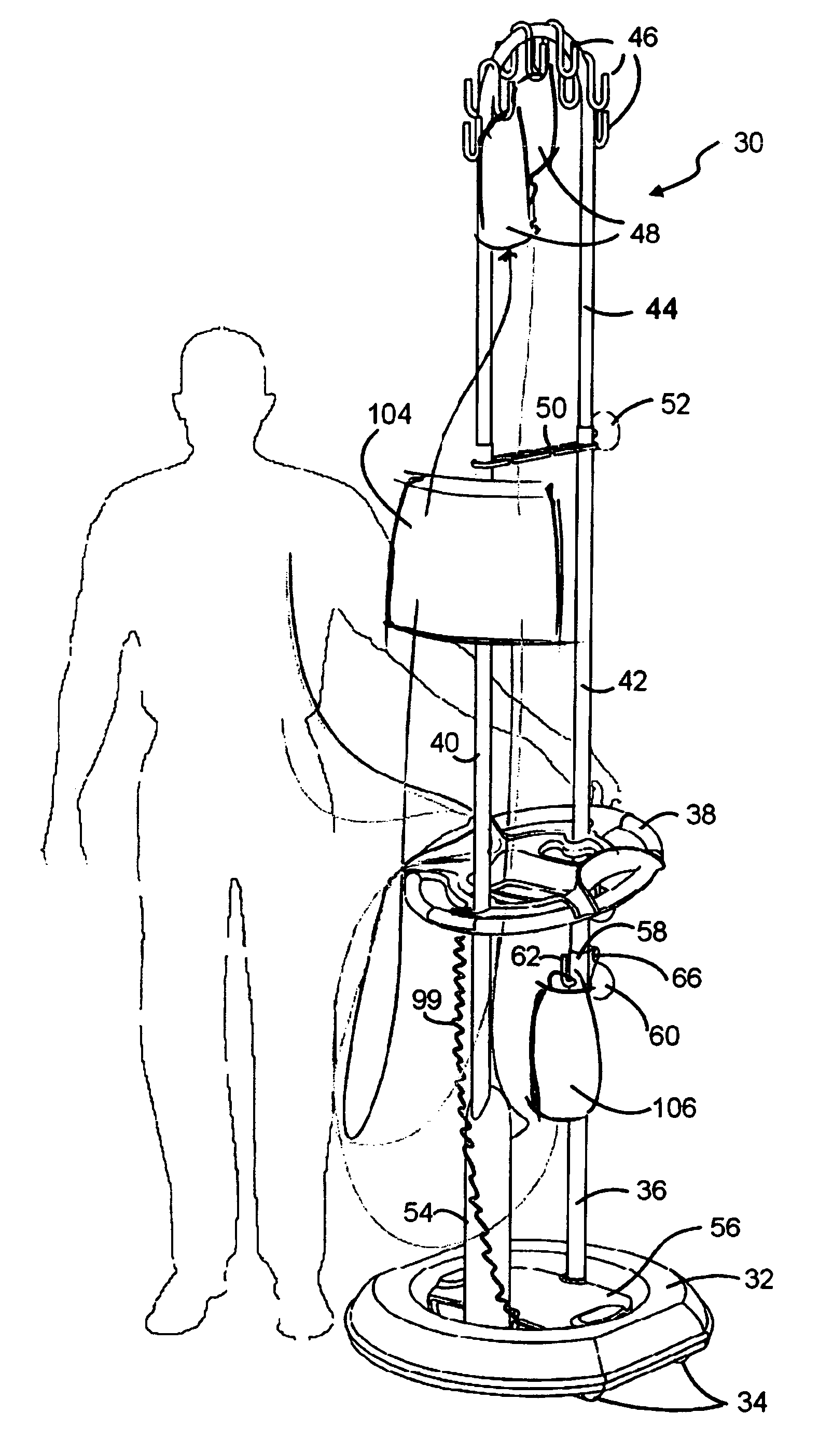
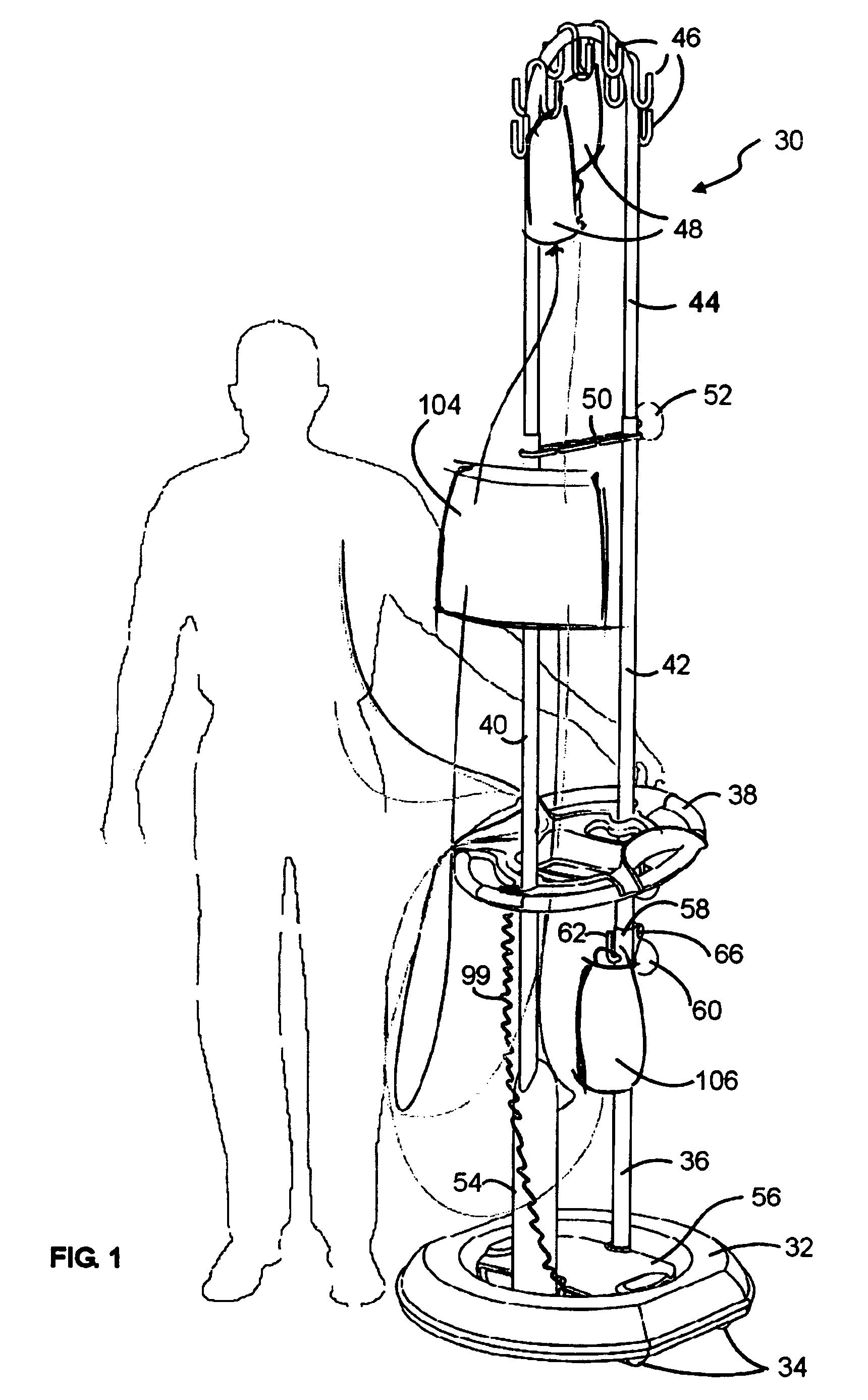
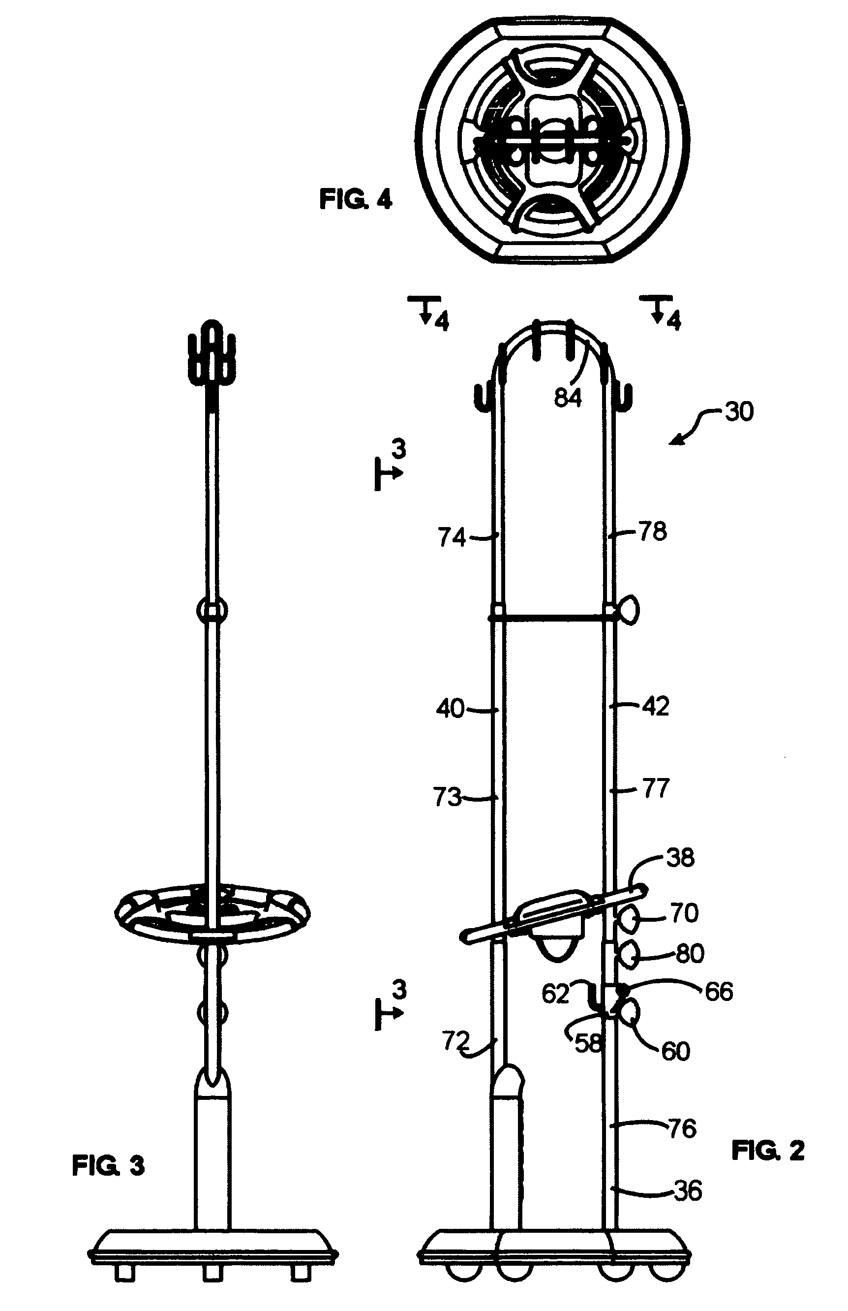
[0030]As shown in FIG. 1, an IV pole 30 includes a base 32 having a set of 3 or more wheels 34 (only two of which are visible in the view shown in FIG. 1), a pole 36 securely coupled to and extending generally upwardly from the base 32, and a handle 38 coupled to the pole 36. As illustrated in FIG. 1, the pole 36 may comprise an inverted U-shaped member having two vertical arms 40, 42 which are securely coupled to and extend generally upwardly from the base 32.

[0031]As also illustrated in FIG. 1, at an uppermost portion 44 of the pole 36, a plurality of hooks 46 or any other suitable means for holding respective intravenous fluid reservoirs 48 (e.g., IV medication bags) are provided.

[0032]A stabilization bar 50 extends laterally between and substantially rigidly interconnects the first and second arms 40, 42 relatively near the uppermost portion 44 of the pole 36. A knob 52 is provided for adjustment of the vertical height of the pole 36, and thus the altitude of the fluid reservoir...


PUM


Abstract

A mobile IV pole has a wheeled base with an enclosure that substantially covers the wheels and a bumper secured to the enclosure. A pole is coupled to the base, and a plurality of hook or other holders are provided for holding intravenous fluid reservoirs. The pole may include first and second arms that extend substantially vertically upwardly from the base, each arm made up of respective lower, central, and upper telescoping tubular portions. The lower portions of the arms are securely coupled to the base, the upper portions are rigidly interconnected with one another, and the central portions of the first and second arms are rigidly interconnected by a stabilization bar which has a plurality of routing channels therein for routing flexible IV tubing. An obliquely oriented handle is coupled to the pole and is axially movable along at least a portion of the pole. The IV pole may be provided with an electrical receptacle having a retractable power cord. A hook or other hanger also may be provided at a lower portion of the pole for hanging a catheter bag, and a further hook, eyelet, or other coupling may be provided for towing the IV pole along with a gurney, wheelchair, or bed, for example.

Description

TECHNICAL FIELD[0001]The present invention relates generally to IV poles, and more particularly, to an IV pole including such features as an adjustable multi-height handle, an enclosed wheel base, and a retractable power cord.BACKGROUND[0002]For many years, patients needing intravenous fluid transfusions have been able to remain ambulatory during such transfusions by using mobile, wheeled IV poles such that the patient, while walking, can roll the IV pole alongside him or her within reach of the length(s) of flexible tubing through which intravenous fluid flows from one or more medication bags to the patient. Early mobile IV poles, however, have suffered from a number of drawbacks.[0003]For example, prior mobile IV poles generally have not had a handle which could easily be adjusted upwardly or downwardly by a patient to accommodate patients of different heights. Prior handles also generally have been oriented horizontally such that patients could not always comfortably or safely gr...

Claims


Application Information

Patent Timeline
Patent Type & Authority Patents(United States)
IPC IPC(8): A61M5/14
CPCA61M5/1415A61M5/1417
Inventor UGENT, CARI LYNNHATCH, PAUL D.BARMORE, CHRIS K.MUELLER, ELIZABETH
Owner SAFEPOLE
Why Eureka
Try Eureka