Split carrier annulus seal assembly for wellhead systems

Active Publication Date: 2005-11-29
DRIL QUIP
View PDF16 Cites 30 Cited by
  • Summary
  • Abstract
  • Description
  • Claims
  • Application Information

AI Technical Summary

Benefits of technology

[0012]The outer member may be a subsea wellhead housing, with the tapered surface on the outer diameter of a tubular hanger forming the inne

Problems solved by technology

Such seals are difficult to design using

Method used


Image

  • Split carrier annulus seal assembly for wellhead systems
  • Split carrier annulus seal assembly for wellhead systems
  • Split carrier annulus seal assembly for wellhead systems

Examples


Example

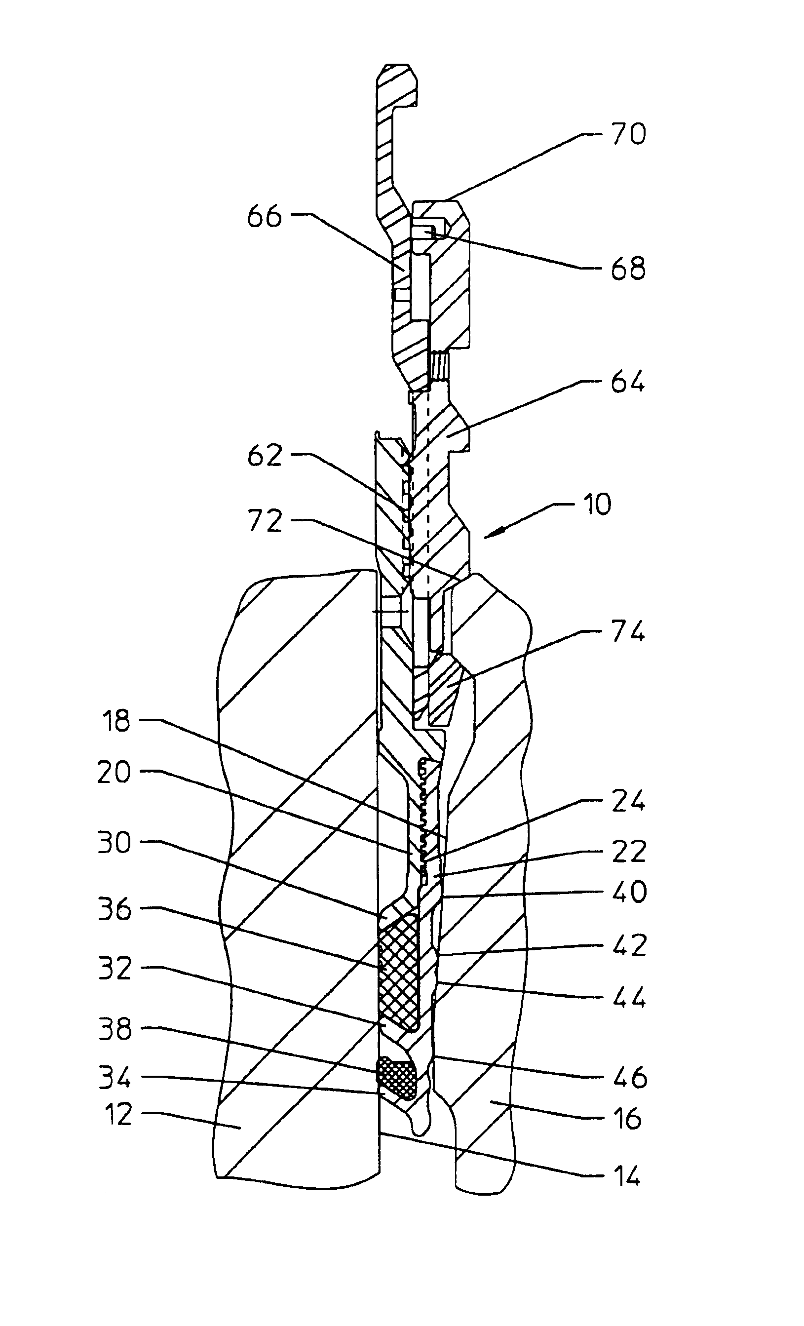
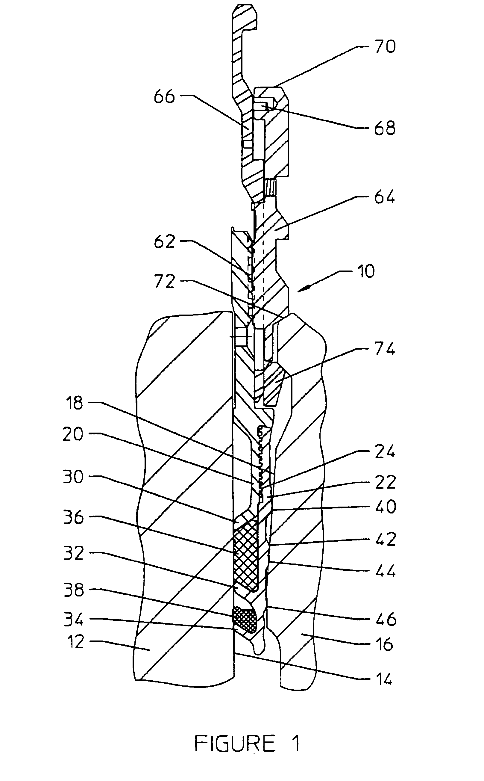
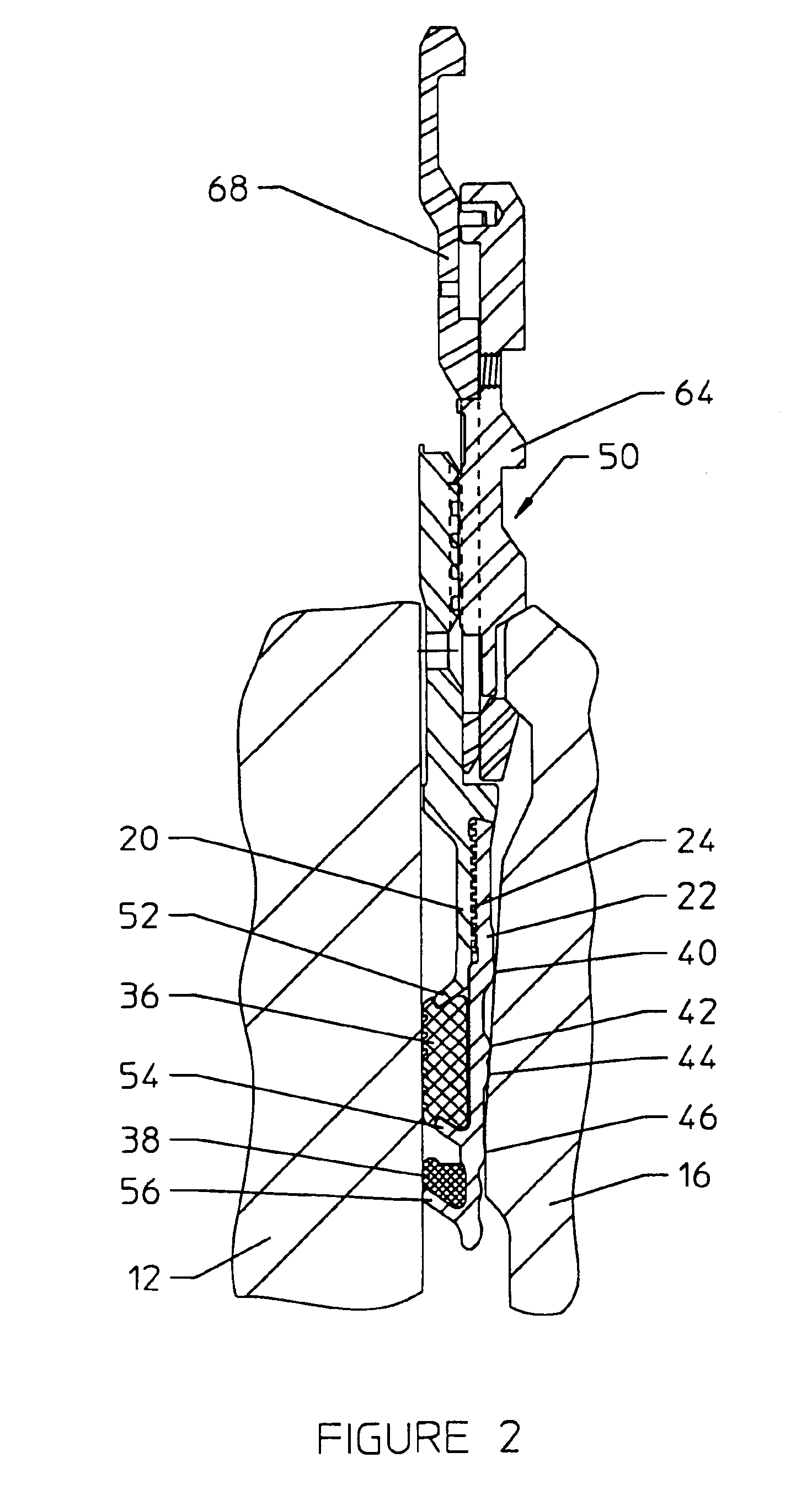
[0017]The seal assembly includes a two-piece seal body or carrier. This design allows a variety of lower temperature complete circular elastomeric seal elements to be easily installed on the seal body, thereby allowing an economical design of a complete seal assembly. This elastomeric seal may be used as a temporary puller seal used during installation, as explained below. A metallic seal element is installed between two axially spaced fingers or stops, each on one of the seal bodies. The seal body includes generally radially extending ribs or fingers for carrying the elastomeric seal element down hole and optionally aiding in metal-to-metal sealing. The two-piece seal body preferably includes a thread for screwing the two halves of the two-piece seal body together. Other securing techniques may be used, such as bolting the two pieces together. Threading of the two-piece seal bodies is preferred, however, since this low cost manufacturing technique easily allows for field replacemen...


PUM


Abstract

The seal assembly 10 seal between a subsea wellhead housing 12 and a casing hanger 16. A metal seal body 20 includes fingers 32 and 34 and one or more elastomeric seals 38. An upper seal body 64 may include threads for engagement with the metal seal body. According the method of the invention, an initial elastomeric seal is first formed, and fluid pressure is applied from above to set the high temperature metal seal.

Description

RELATED CASE[0001]This application claims priority from U.S. Ser. No. 60 / 372,399 filed on Apr. 12, 2002, and entitled “Downhole Radial Set Packer Element”, hereby incorporated by reference.FIELD OF THE INVENTION[0002]The present invention relates to the wellhead system with an annulus seal assembly and, more particularly, relates to a spit carrier annulus seal assembly suitable for use between a subsea wellhead housing and a casing hanger.BACKGROUND OF THE INVENTION[0003]In a subsea wellhead system, an annulus seal assembly may seal the annulus between the wellhead housing and the OD of the casing hanger. This seal (or seal assembly) is conventionally run in with a running tool, which also runs and lands the casing hanger. The running tool may be manipulated so as to cause the seal to be set and then tested, typically from a pressure above to a pressure at or below the working pressure of the wellhead system.[0004]Annulus seal assemblies have performed well in subsea wellhead system...

Claims


Application Information

Patent Timeline
IPC IPC(8): E21B33/00E21B33/035E21B33/04E21B33/12
CPCE21B33/035E21B33/04E21B33/1212E21B33/1216E21B2033/005E21B2200/01
Inventor REIMERT, LARREY E.MILBERGER, LIONEL J.
Owner DRIL QUIP
Why Eureka
Try Eureka