
Microcontact structure for neuroprostheses for implantation on nerve tissue and method therefor

a microcontact structure and neuroprosthesis technology, applied in the field of implantable microcontact structures for neuroprosthesis, can solve the problems of not having mechanisms to carry out, no devices and methods provided for microcontact structure explantation, and inability to minimise the spacing between microelectrodes

Inactive Publication Date: 2005-11-29
PIXIUM VISION SA
View PDF14 Cites 21 Cited by
  • Summary
  • Abstract
  • Description
  • Claims
  • Application Information

AI Technical Summary

Benefits of technology

[0010]The object of the present invention is to eliminate these disadvantages and to provide a microcontact structure that can be introduced in compressed form into the body and can be reversibly anchored on the nerve tissue.SUMMARY OF THE INVENTION

Problems solved by technology

A disadvantage of the known microcontact structures is that no devices and methods are provided for explantation of the microcontact structure.
Furthermore, known microcontact structures do not have mechanisms that carry out matching of the microcontact structure to the shape of the tissue to be contacted.
It is therefore not possible to minimise the spacing between the microelectrodes and the neurones to be stimulated in the nerve tissue.
A further disadvantage of known microcontact structures is that they do not have the possibility of spontaneous attachment of the microcontact structure to the nerve tissue.
A disadvantage of the currently designed or available microcontact structures for epiretinal optic prostheses is that they lack features that permit incorporation in the eye in spatially compressed shape and complicated surgical techniques are therefore necessary.
This difficulty will heighten in the future as the spatial dimensions of the microcontact structures become greater with an increasing number of contacts.
Furthermore, the available microcontact structures for epiretinal optic prostheses are incapable of covering the neurones of the retina that connect the region of sharpest vision with a high microcontact density since such neurones are situated in so-called parafoveal cell craters that are distinguished by a spatial crater structure.

Method used


Image

  • Microcontact structure for neuroprostheses for implantation on nerve tissue and method therefor
  • Microcontact structure for neuroprostheses for implantation on nerve tissue and method therefor
  • Microcontact structure for neuroprostheses for implantation on nerve tissue and method therefor

Examples


Embodiment Construction

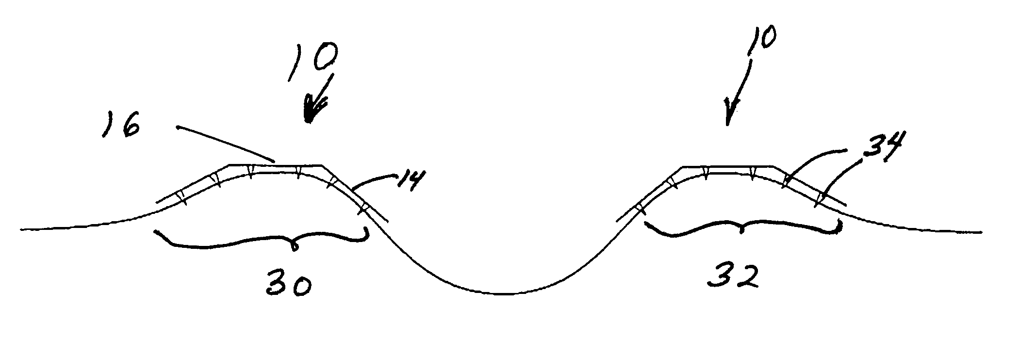
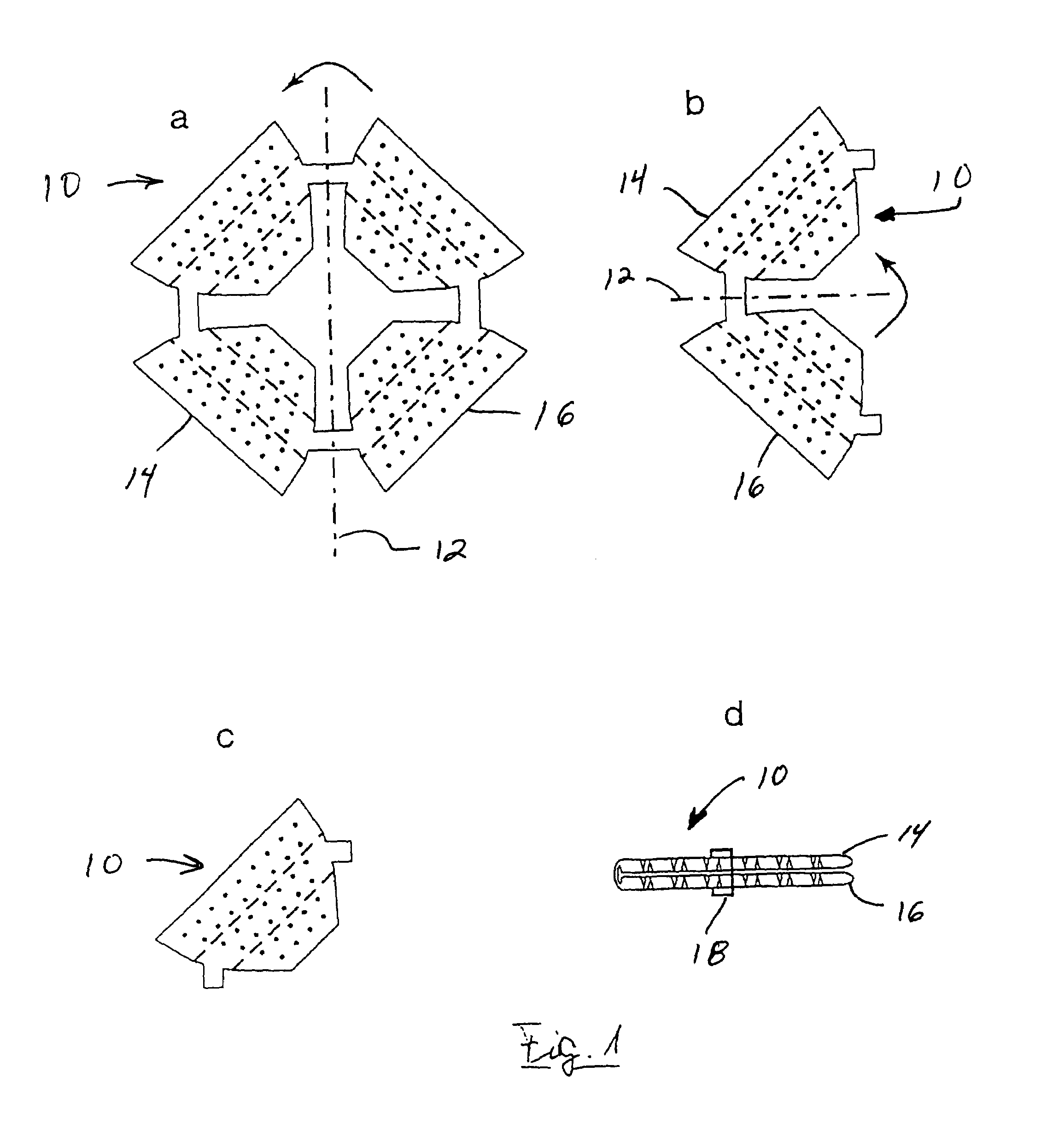
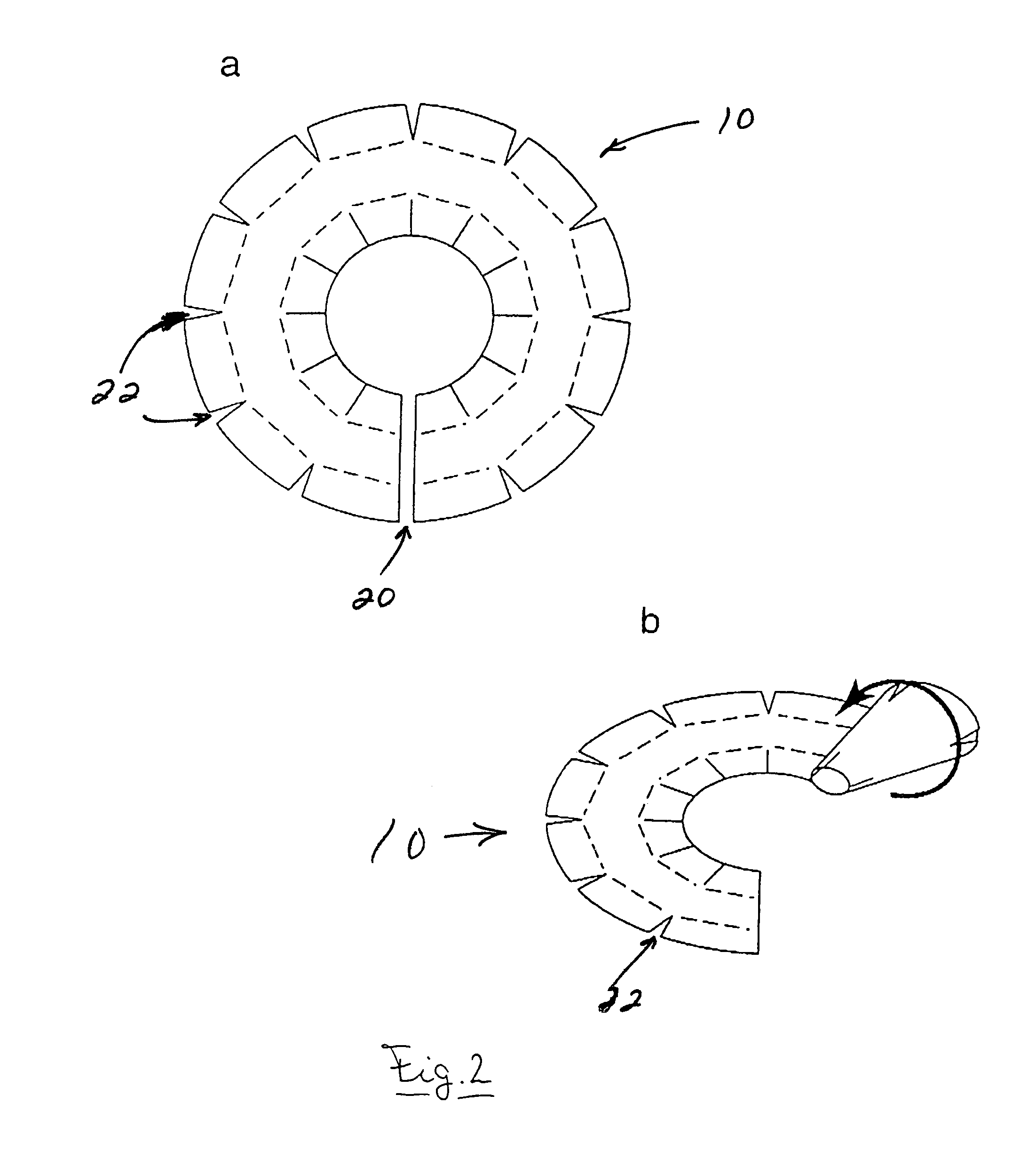
[0021]An advantageous device comprising a spatially adaptive microcontact structure for neuroprostheses for implantation at nerve tissue embodies the feature that the microcontact structure can be produced as a planar, two-dimensional structure using current methods for producing microcontact structures (for example on a silicon, silicon or polyimide base (see FIGS. 1–4)).

[0022]In the embodiments depicted in FIG. 1a and 1b a two-dimensional microcontact structure is portrayed. This structure comprises two regions, items 14 and 16, that are foldable about and axis 12. FIG. 1c depicts a simpler embodiment which depicts a microcontact structure which capable of being rolled. Accordingly, these embodiments relate to a microcontact structure that can be folded or rolled very compactly in a second step for transportation purposes in a surgical procedure. Subsequent to its delivery to the implantation point, the structure can not only be unfolded planarly in a third step but may be folded ...


PUM


Abstract

The invention relates to a spatially adaptive, implanted microcontact structure for neuroprostheses suitable for treating functional disorders of the nervous system for the purpose of reversible anchorage on nerve tissue. The spatially adaptive microcontact structure (RAM) is characterized in particular in that an optimum contact or active connection to nerve tissue is ensured. The implanted microcontact structure comprises subareas that are movable relative to one another and that can be brought into at least two permanent desired positions relative to one another and that can be brought into a desired position during implantation for the purpose of mechanical anchorage to the nerve tissue to be contacted and can also be brought out of one desired position into another during explantation to release the anchorage.

Description

THE FIELD OF THE INVENTION[0001]The invention relates to an implantable microcontact structure for neuroprostheses for treating functional disorders of the nervous system for the purpose of reversible anchorage on nerve tissue.BACKGROUND[0002]Several microcontact structures for partly implanted neuroprostheses are known whose spatial microcontact arrangement is fixed by a rigid, preshaped area (see for example in U.S. Pat. No. 5,215,088).[0003]Several microcontact structures for partially implanted neuroprostheses are known whose spatial microcontact arrangement is fixed by a partly elastic, flexible, preshaped area and that can alter as a result of the type of implant attachment and also as a result of passive matching to the tissue shape in the implant area (see for example DE-A-4424753).[0004]The production of such a microcontact structure is disclosed (for example) in “Flexible, polyimide-based neural interfaces” Stieglitz et al, J-U. Proceedings of the Seventh International Con...

Claims


Application Information

Patent Timeline
IPC IPC(8): A61N1/05
CPCA61N1/0543A61N1/0551A61N1/0558
Inventor ECKMILLER, ROLFHUNERMANN, RALPHBECKER, MICHAEL
Owner PIXIUM VISION SA
Learn More