Control system

Active Publication Date: 2005-12-06
GOODRICH CONTROL SYST LTD
View PDF7 Cites 39 Cited by
  • Summary
  • Abstract
  • Description
  • Claims
  • Application Information

AI Technical Summary

Benefits of technology

[0018]Advantageously, therefore, the control means may be arranged to control the first and second electric motors such that, in normal operation, both of said first and said second electric motors drive said pump means but in the event of failure or incorrect operation of one

Problems solved by technology

Correct operation of the pump is essential to the performance of the engine since failure of the fuel supply may cause the

Method used


Image

  • Control system
  • Control system
  • Control system

Examples


Embodiment Construction

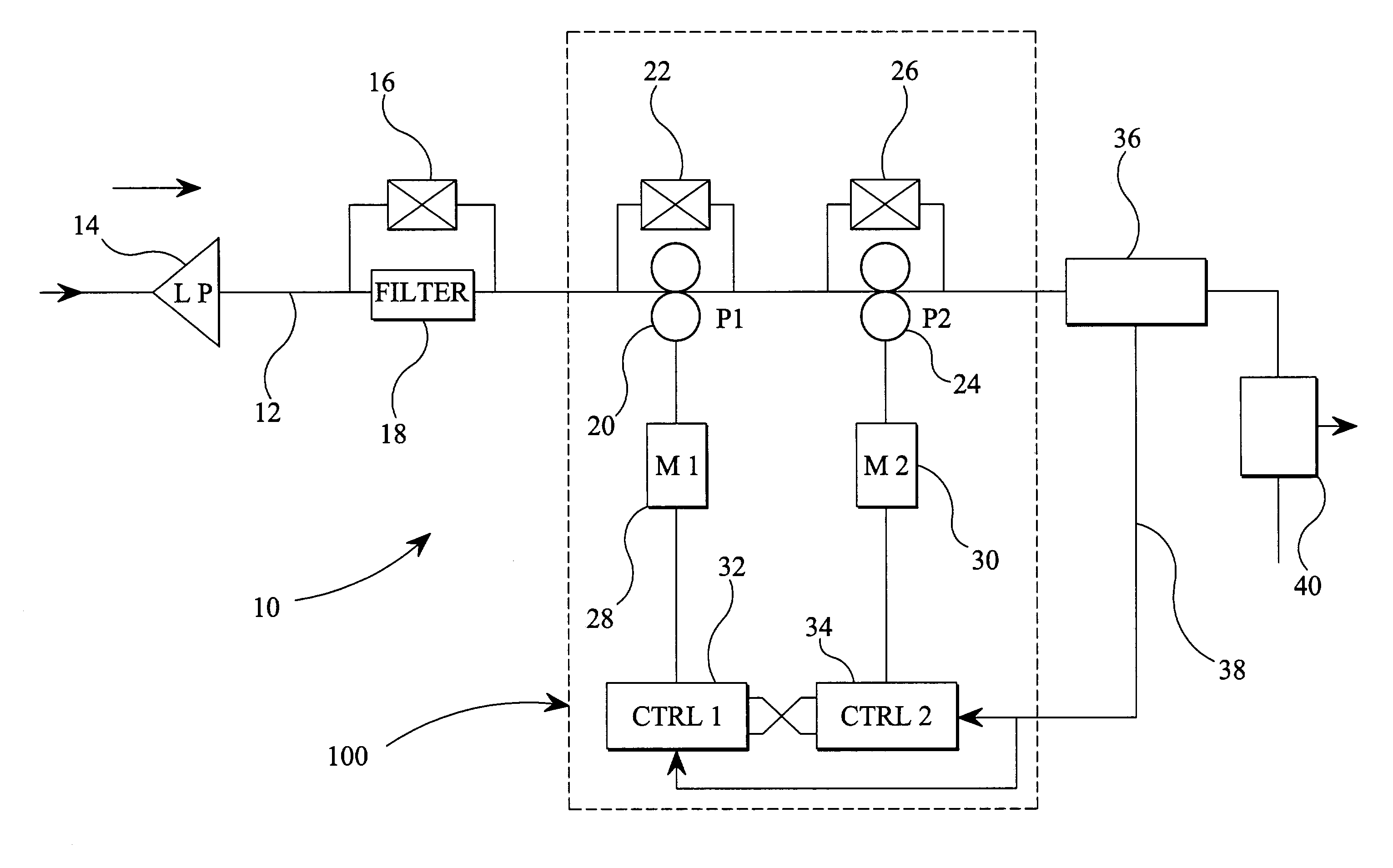
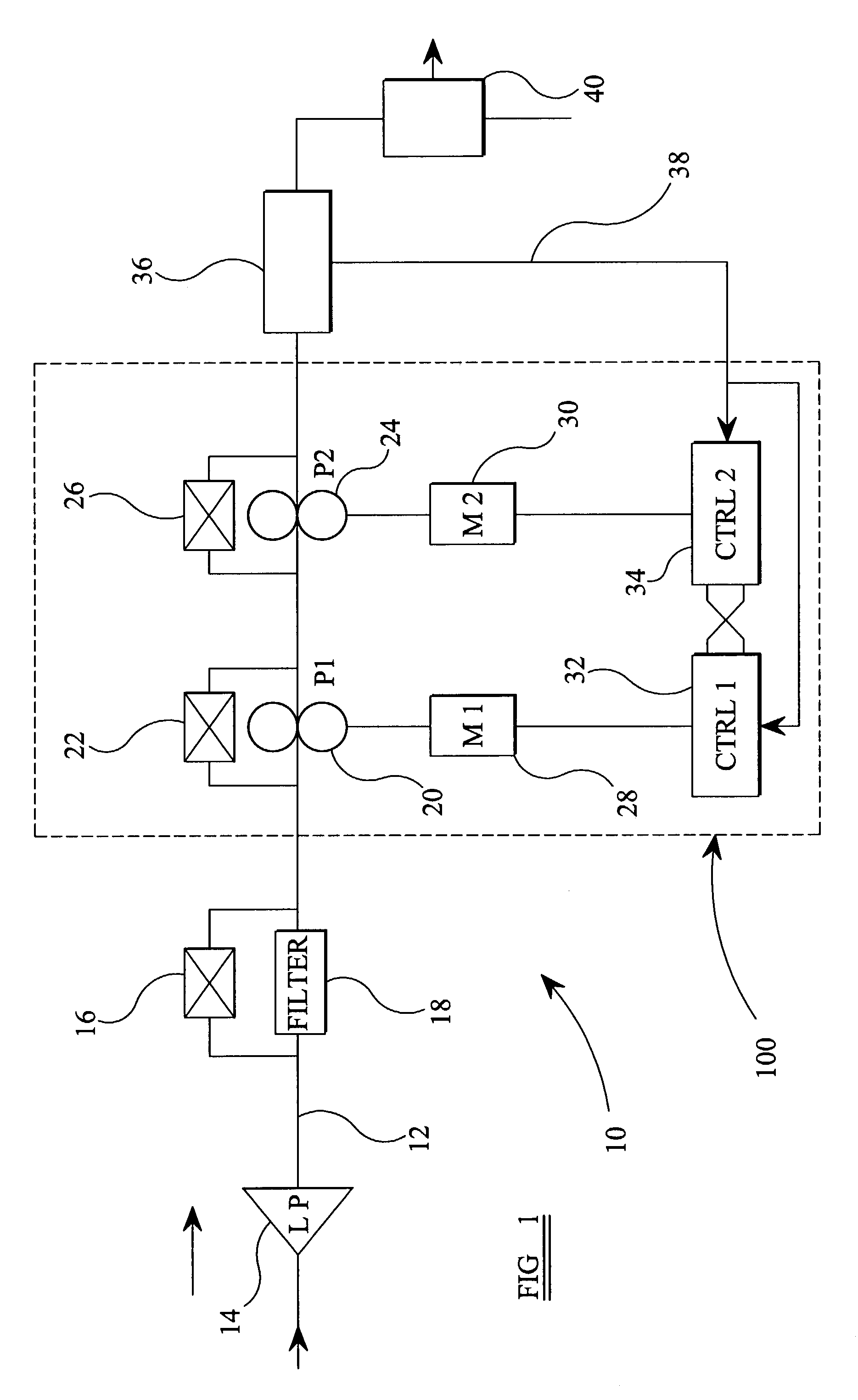
[0022]Referring to FIG. 1, a first form of control system according to the invention is shown generally at 10. Fuel supplied to the system 10 from a fuel tank or other store (not shown) on a fuel line 12 by means of a low pressure pump 14. The fuel is passed, at a low pressure, through a filter 18 across which a bypass valve 16 is connected.

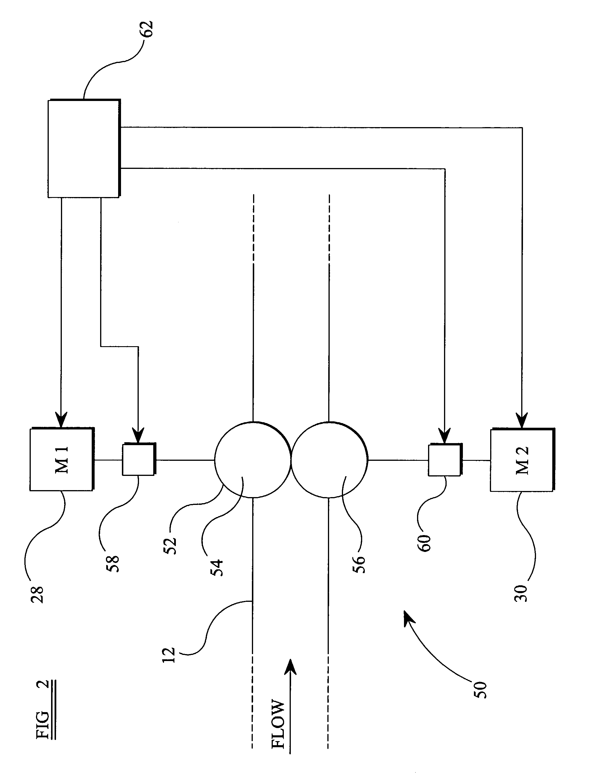
[0023]Pump means including first and second positive displacement fuel pumps 20, 24 are connected to the fuel line 12 in a series arrangement, the first fuel pump 20 being located on the fuel line 12“upstream” of the second fuel pump 24. Each of the first and second fuel pumps 20, 24 is arranged to be driven by a respective electric motor 28, 30. Control means, in the form of first and second motor controllers 32, 34, are connected to the first and second electric motors 28, 30 respectively and are arranged to control the operation and speed thereof. Although the first and second motor controllers 32, 34 are operable to control the operation of t...


PUM


Abstract

A fuel control system for controlling the supply of fuel to an engine, the control system comprising:
    • pump means for providing a flow of fuel to said engine;
    • first and second drive means for driving said pump means; and,
    • control means for controlling said first and second drive means; wherein, said control means is arranged to control said first and second drive means such that in the event of failure of one of said first and second drive means, said pump means is driven by the other of said first and second drive means.

Description

BACKGROUND OF THE INVENTION[0001]The present invention relates to a control system for controlling the fuel supply to a combustion engine or the like.[0002]Combustion engines, including internal combustion engines and gas turbine engines, generally require a constant, though often variable, flow of fuel to be supplied thereto in order to operate correctly. Fuel, usually in a liquid state, is pumped from a tank or other fuel store along a fuel line by means of a fuel pump and supplied to the engine at a predetermined pressure. The pump is often driven by means of a motor whose speed can be controlled so as to increase or decrease the flow rate of the fuel supplied to the engine by the pump.[0003]Correct operation of the pump is essential to the performance of the engine since failure of the fuel supply may cause the engine to shut down. This may have potentially dangerous consequences, for example, where the engine is an aircraft engine. It would be advantageous to provide a fuel con...

Claims


Application Information

Patent Timeline
IPC IPC(8): F02D41/22F02D41/30F02M37/18
CPCF02D41/3082F02M37/18F02D41/221F02D2041/226
Inventor MUDWAY, JOHN ANTHONYMAKER, PAUL MANWARING
Owner GOODRICH CONTROL SYST LTD
Why Eureka
Try Eureka