Light emitting diode device

a technology of light-emitting diodes and diodes, which is applied in the field of light-emitting diodes, can solve the problems of hot spots on the screen of lcd, further reducing the horizontal emission efficiency of light-emitting diodes, etc., and achieves the effect of enhancing horizontal emission efficiency and preventing hot spots

Inactive Publication Date: 2005-12-06
SAMSUNG ELECTRONICS CO LTD
View PDF4 Cites 146 Cited by
  • Summary
  • Abstract
  • Description
  • Claims
  • Application Information

AI Technical Summary

Benefits of technology

[0018]The present invention has been made in view of the above problems, and it is an object of the present invention to provide a light emitting diode device, which completely changes the path of light emitted upwardly at the center of the light emitting diode device to the horizontal direction, thereby enhancing horizontal emission efficiency together with preventing a hot spot.
[0019]In accordance with one aspect of the present invention, the above and other objects can be accomplished by the provision of a light emitting diode device, comprising: a package formed with a terminal for applying an electrical signal; one or more LED chips mounted on the package such that the LED chips are electrically connected to the terminal; a lens formed to surround the LED chips on the package for changing path of light emitted from the LED chips to the horizontal direction using the differences of refraction rates of the media; and a reflector formed on the lens for reflecting the light, emitted above the lens without being refracted in the horizontal direction by the lens, to the horizontal direction. The light emitting diode device completely shields the light emitted above the lens, and changes the path of light in the perfectly horizontal direction, thereby enhancing horizontal emission efficiency of the light, and absolutely preventing a hot spot from being generated when using the liquid emitting diode device for the backlight unit of the liquid crystal display.

Problems solved by technology

Meanwhile, in the light emitting diode device as described above, there sometimes occurs a problem in that a portion of the light incident at an angle deviated from an optical design range is emitted directly above the lens without being refracted at the reflective surfaces.
Such a problem can become more apparent in the case where a large LED chip is mounted on the light emitting diode device, thereby further reducing horizontal emission efficiency of the light emitting diode device.
Moreover, when the backlight unit of the LCD is realized using the light emitting diode device as described above, due to the light emitted in the perpendicular direction from the LCD device, there occurs a hot spot on a screen of the LCD.

Method used


Image

  • Light emitting diode device
  • Light emitting diode device
  • Light emitting diode device

Examples


Embodiment Construction

[0031]Now preferred embodiments of the present invention will be described in detail with reference to the accompanying drawings so that those skilled in the art may easily understand and repeat the present invention.

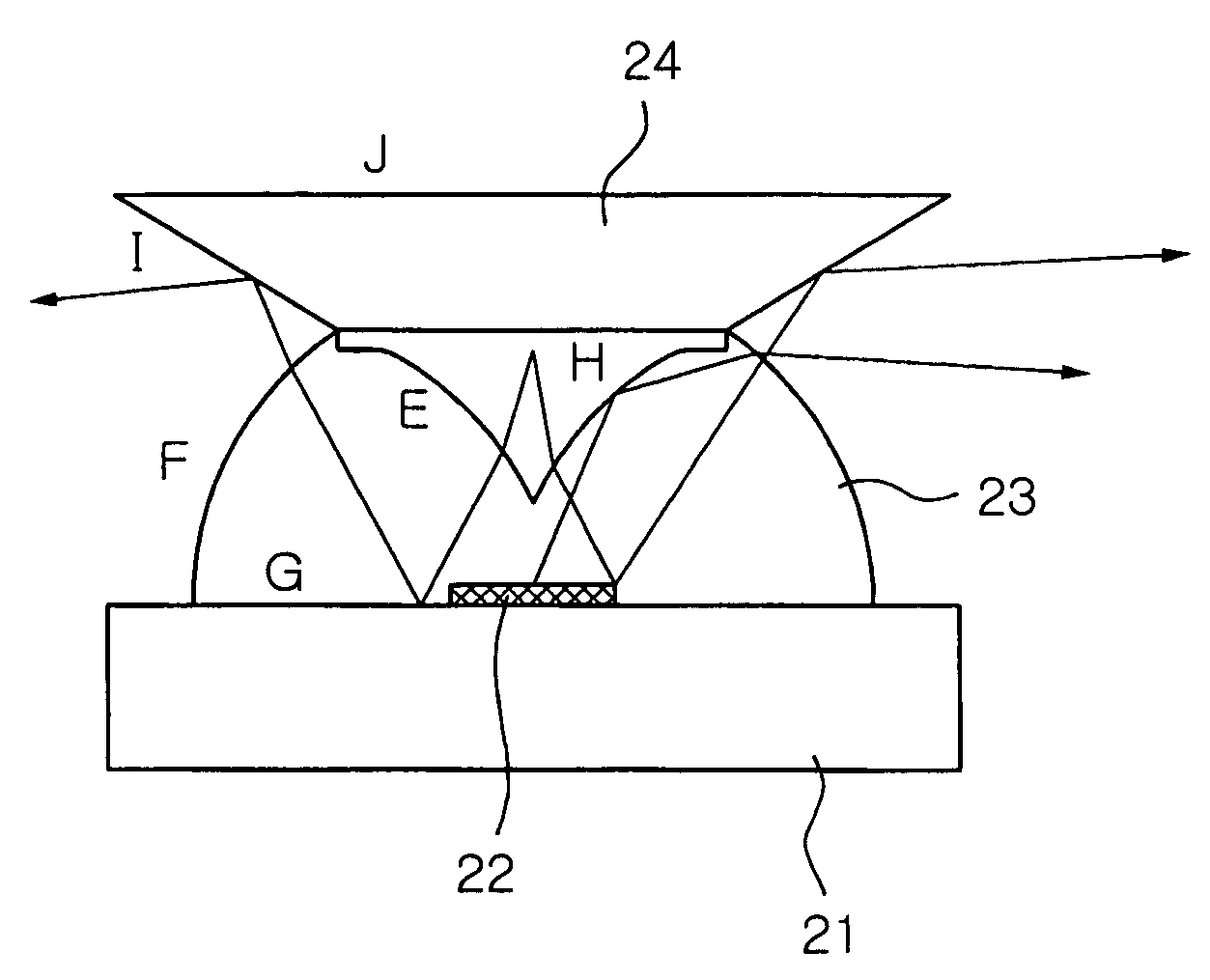
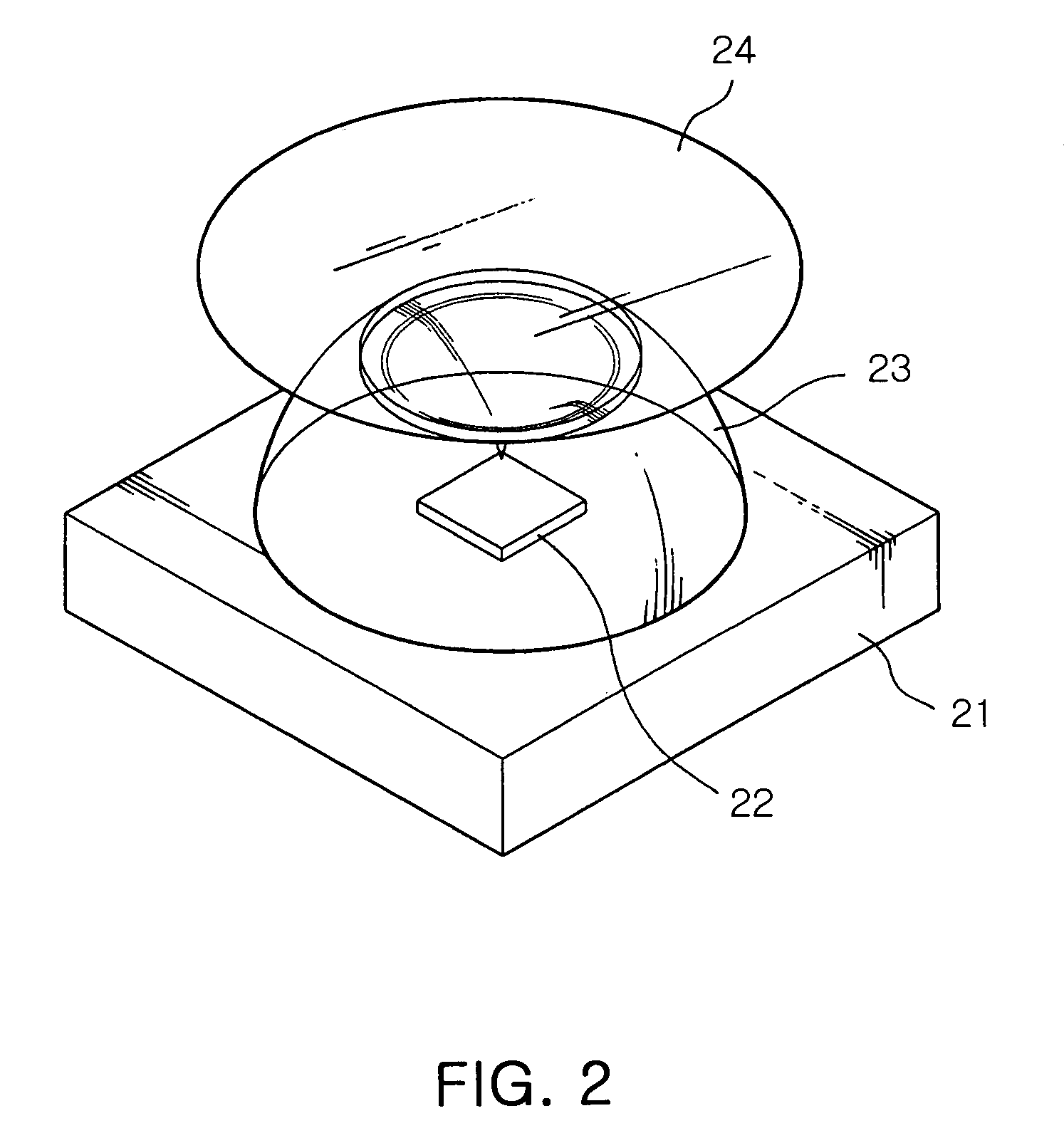
[0032]FIG. 2 is a cross sectional view illustrating a light emitting diode device according to the present invention, and FIG. 3 is an exploded perspective view illustrating the light emitting diode device according to the present invention.

[0033]Referring to FIGS. 2 and 3, a light emitting diode device comprises a package 21 formed with a terminal for applying an electrical signal, one or more LED chips 22 mounted on the package 21, a lens 23 formed to surround the LED chips at an upper portion of the package 21 for changing the path of light emitted from the LED chips 21 to the horizontal direction, and a reflector 24 for reflecting the light, emitted above the lens 23 without being refracted in the horizontal direction at the lens 23, to the horizontal direction.

[003...


PUM

PropertyMeasurementUnit
refraction ratesaaaaaaaaaa
transparentaaaaaaaaaa
translucentaaaaaaaaaa

Abstract

Disclosed herein is a light emitting diode (LED) device. The light emitting diode device comprises a package formed with a terminal for applying an electrical signal, one or more LED chips mounted on the package such that the LED chips are electrically connected to the terminal, a lens formed to surround the LED chips on the package for changing path of light emitted from the LED chips to the horizontal direction with the difference of the refraction rates of the media, and a reflector formed on the lens for reflecting the light, emitted above the lens without being refracted in the horizontal direction at the lens, to the horizontal direction. The LED device reflects the light, which is deviated from the optical design range of the lens and emitted above the lens, back to the lens, thereby preventing the hot spot from being generated, and enhancing horizontal emission efficiency of the light.

Description

RELATED APPLICATIONS[0001]The present application is based on, and claims priority from, Korean Application Number 2004-37763, filed May 27, 2004, the disclosure of which is hereby incorporated by reference herein in its entirety.BACKGROUND OF THE INVENTION[0002]1. Field of the Invention[0003]The present invention relates to a light emitting diode device, which can be used for a light source of a backlight in a liquid crystal display (LCD), and more particularly to a light emitting diode device, which completely changes the path of light emitted upwardly at the center of the light emitting diode to the horizontal direction, thereby enhancing horizontal emission efficiency, together with preventing a hot spot.[0004]2. Description of the Related Art[0005]A light emitting diode (LED) is a semiconductor light emitting device, which emits various colors of light, with light sources being constituted by compound semiconductors made of various materials, such as GaAs, AlGaAs, GaN, InGaN an...

Claims


Application Information

Patent Timeline
Patent Type & Authority Patents(United States)
IPC IPC(8): H01L29/22G02F1/13357H01L33/54H01L33/60
CPCH01L33/54H01L33/60A47G19/2205B82Y30/00A47G2400/02
Inventor KIM, HYUNG SUKPARK, YOUNG SAMHAHM, HUN JOOPARK, JUNG KYUJEONG, YOUNG JUNE
Owner SAMSUNG ELECTRONICS CO LTD
Why Eureka
Try Eureka