Series resonant inductive charging circuit

a technology of inductive charging and series resonance, which is applied in the direction of electrochemical generators, secondary cell servicing/maintenance, transportation and packaging, etc., can solve the problems of disadvantageous conductive charging of batteries, short circuits, and electrical shock to users

Active Publication Date: 2005-12-06
STRYKER CORP
View PDF5 Cites 173 Cited by
  • Summary
  • Abstract
  • Description
  • Claims
  • Application Information

AI Technical Summary

Problems solved by technology

Conductive charging of a battery can be disadvantageous, however, in certain environments, such as where fluids could come into direct contact with exposed electrical contacts.
This condition could result in short circuiting, electrical shock to the user, fire and / or corrosion of the contacts.
One example of a device that is subject to such an environment is a battery-powered cordless electric toothbrush, where problems could result if exposed electrical contacts were to come into direct contact with fluid.
One problem with inductive charging techniques of the prior art is inefficient power transfer, resulting in undesirably long charge times. One way to circumvent this problem would be through the use of a large amplifier in the charging unit in order to increase the inductive power transfer.
However, such an approach tends to be more expensive, to require a larger charging device (to accommodate the amplifier), and to generate excessive heat and exacerbates electromagnetic compatibility (EMC) problems.

Method used


Image

  • Series resonant inductive charging circuit
  • Series resonant inductive charging circuit

Examples


Embodiment Construction

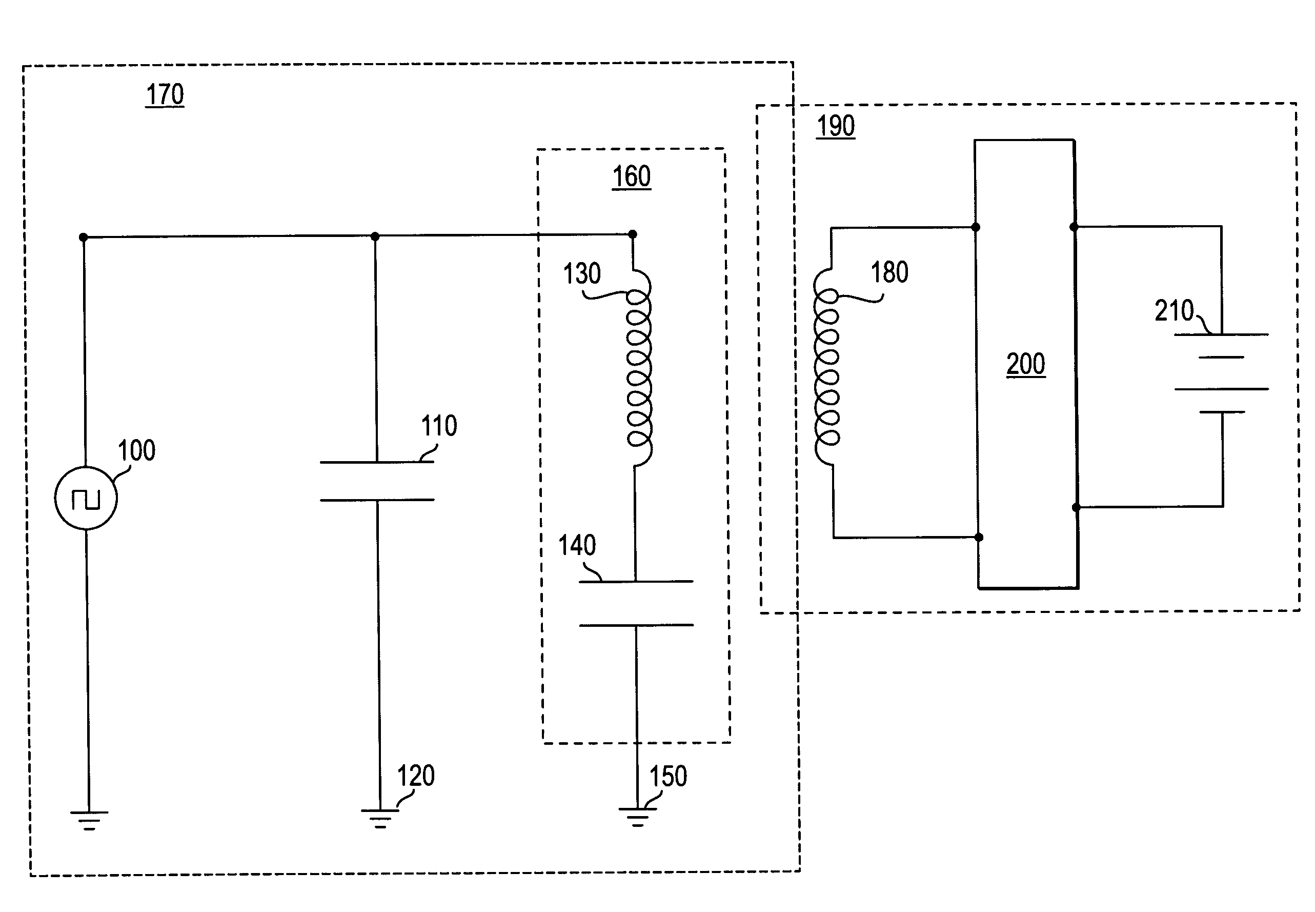
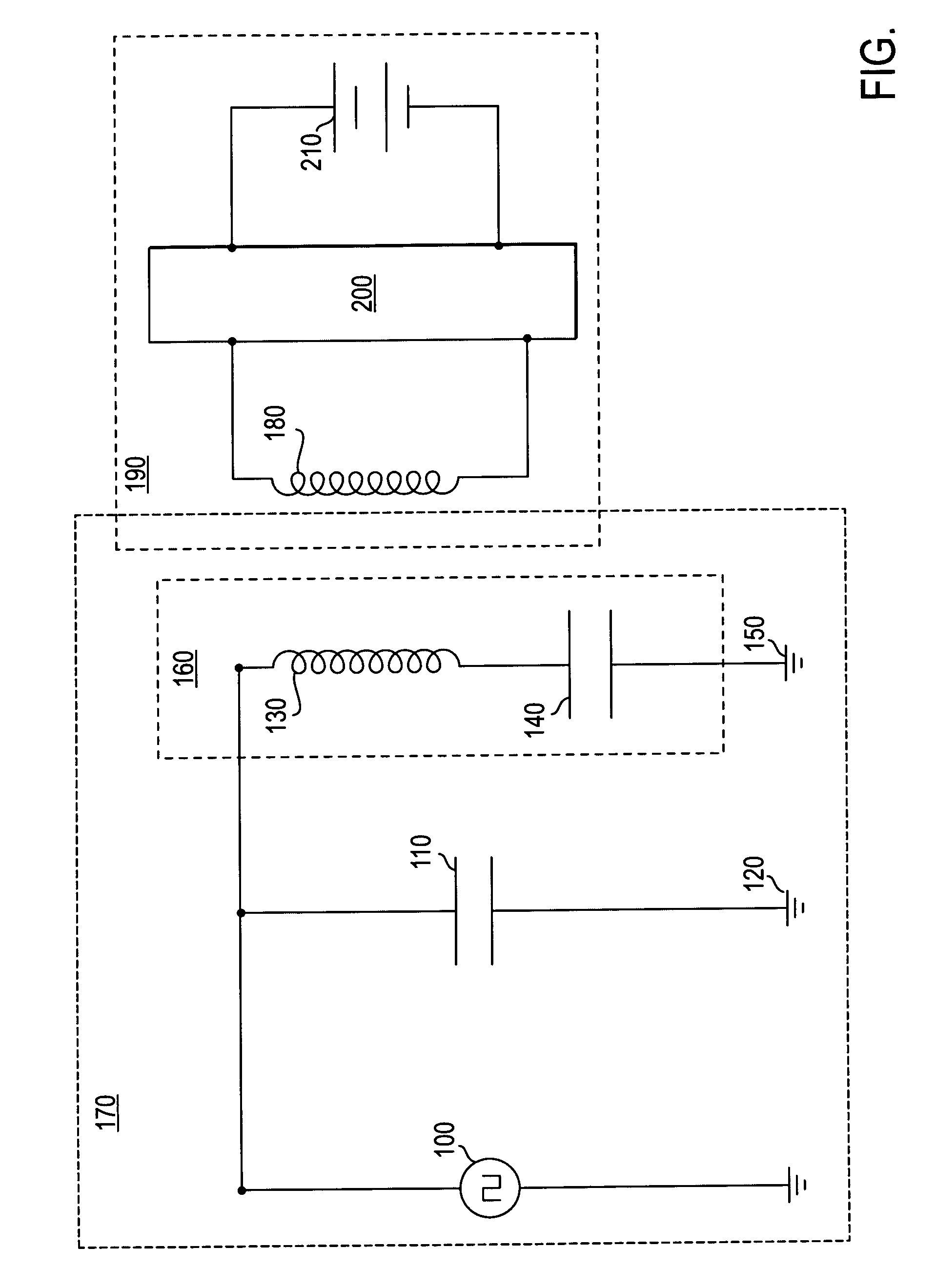
[0011]A method and apparatus to inductively charge a power supply are described. Note that in this description, references to “one embodiment” or “an embodiment” mean that the feature being referred to is included in at least one embodiment of the present invention. Further, separate references to “one embodiment” or “an embodiment” in this description do not necessarily refer to the same embodiment; however, such embodiments are also not mutually exclusive unless so stated, and except as will be readily apparent to those skilled in the art from the description. For example, a feature, structure, act, etc. described in one embodiment may also be included in other embodiments. Thus, the present invention can include a variety of combinations and / or integrations of the embodiments described herein.

[0012]As described in greater detail below, an apparatus in accordance with the present invention allows for inductively charging a rechargeable power supply with greater efficiency and redu...


PUM

PropertyMeasurementUnit
resonant frequencyaaaaaaaaaa
frequencyaaaaaaaaaa
poweraaaaaaaaaa

Abstract

An apparatus to charge a power supply inductively, with increased efficiency due to resonance, comprises an LC series resonance circuit formed by a capacitor and a primary inductive coil coupled in series with the capacitor, and a secondary inductive coil positioned such that power is inductively transferred from the primary coil to the secondary coil. The LC circuit has a natural resonant frequency, wherein the primary coil of the resonance circuit is coupled to receive power from a source oscillating at the natural resonant frequency. The secondary coil is further coupled to the power supply so that power induced in the secondary coil causes the power supply to be charged.

Description

FIELD OF THE INVENTION[0001]At least one embodiment of the present invention pertains to inductive charging of a cordless electric device, and more particularly, to the use of an LC series resonance circuit used in a charging device in order to increase the efficiency of inductive power transfer between a primary and secondary inductor.BACKGROUND[0002]Many cordless electric devices use rechargeable batteries as a source of power. These batteries can be permanently contained within a cordless device, or included as a removable battery pack. To charge such batteries, power is normally transferred to the batteries by a conductive connection between the battery and a charging device.[0003]Conductive charging of a battery can be disadvantageous, however, in certain environments, such as where fluids could come into direct contact with exposed electrical contacts. This condition could result in short circuiting, electrical shock to the user, fire and / or corrosion of the contacts. One exam...

Claims


Application Information

Patent Timeline
Patent Type & Authority Patents(United States)
IPC IPC(8): H01M10/42H01M10/46H02J7/02
CPCH02J7/025H01M10/42Y02E60/10H02J50/12H02J7/00
Inventor WELLS, BRANNON P.
Owner STRYKER CORP
Why Eureka
Try Eureka