Signal processor unit and digital information receiver with detachable card module

a technology of digital information and processor unit, applied in the field of digital information receiver unit, can solve the problems of increasing the difficulty of viewing, and increasing the difficulty of operation, so as to prevent the large influence of the overall receiver unit, prevent the unfair practice, and prevent the effect of large influence on the overall receiver uni

Inactive Publication Date: 2005-12-06
KK TOSHIBA
View PDF14 Cites 16 Cited by
  • Summary
  • Abstract
  • Description
  • Claims
  • Application Information

AI Technical Summary

Benefits of technology

[0018]Also, it is another object of the present invention to provide a digital broadcasting receiver unit which is able to decide whether or not the card module as the second unit being connected to the receiver unit main body as the first unit can function correctly, and then disconnect functionally the defective second unit from the first unit to thus prevent the large influence upon the overall receiver unit.
[0019]Also, it is another object of the present invention to provide a digital broadcasting receiver unit which is able to detect the card module as the second unit which is illegally connected to the receiver unit main body as the first unit, and then disconnect functionally the illegal second unit from the first unit by switching the signals via a switch to bypass the second unit being illegally connected, to thus prevent the unfair practice as well as the large influence upon the overall receiver unit.

Problems solved by technology

In recent years, a plurality of enterprises for providing the digital satellite broadcasting service have been launched and thus such inconvenience is caused that different receiving units must be established according to individual enterprises.
However, the request to take always such care is hard for the viewer.
Particularly, when the new card module whose connection order must be taken into consideration is connected in the situation that the card module has already been inserted, the card module which has already been inserted must be taken out once from the slot, whereby operations become troublesome.
For example, in case the front card module and the rear card module must be exchanged, the operation becomes further troublesome.
In addition, such digital broadcasting receiver unit has the problem discussed in the following.
Accordingly, if any trouble is caused in the card module, especially if the broadcasting signal system cannot be propagated to the succeeding stage, malfunction of the system in the succeeding stage is brought about or the system in the succeeding stage is brought into its inoperable condition.
Therefore, not only the function of the defective card module is merely lost, but also the function for receiving the broadcasting via the channel which does not utilize the function of this card module is lost.
As a result, there has been the problem such that the overall receiving system is largely affected by the defective card module.
Furthermore, such digital broadcasting receiver unit has the problem discussed in the following.
Accordingly, there has been the problem that, even if the illegal card module is connected for the purpose of unfair practice such as copying operation of the broadcasting signals, etc., the digital broadcasting receiver unit permits such unfair practice.
Moreover, there has been the problem that, the illegal card module is connected to the card module slots arranged in the daisy-chain connection, the overall receiving system is largely affected by the illegal card module.

Method used


Image

  • Signal processor unit and digital information receiver with detachable card module
  • Signal processor unit and digital information receiver with detachable card module
  • Signal processor unit and digital information receiver with detachable card module

Examples


first embodiment

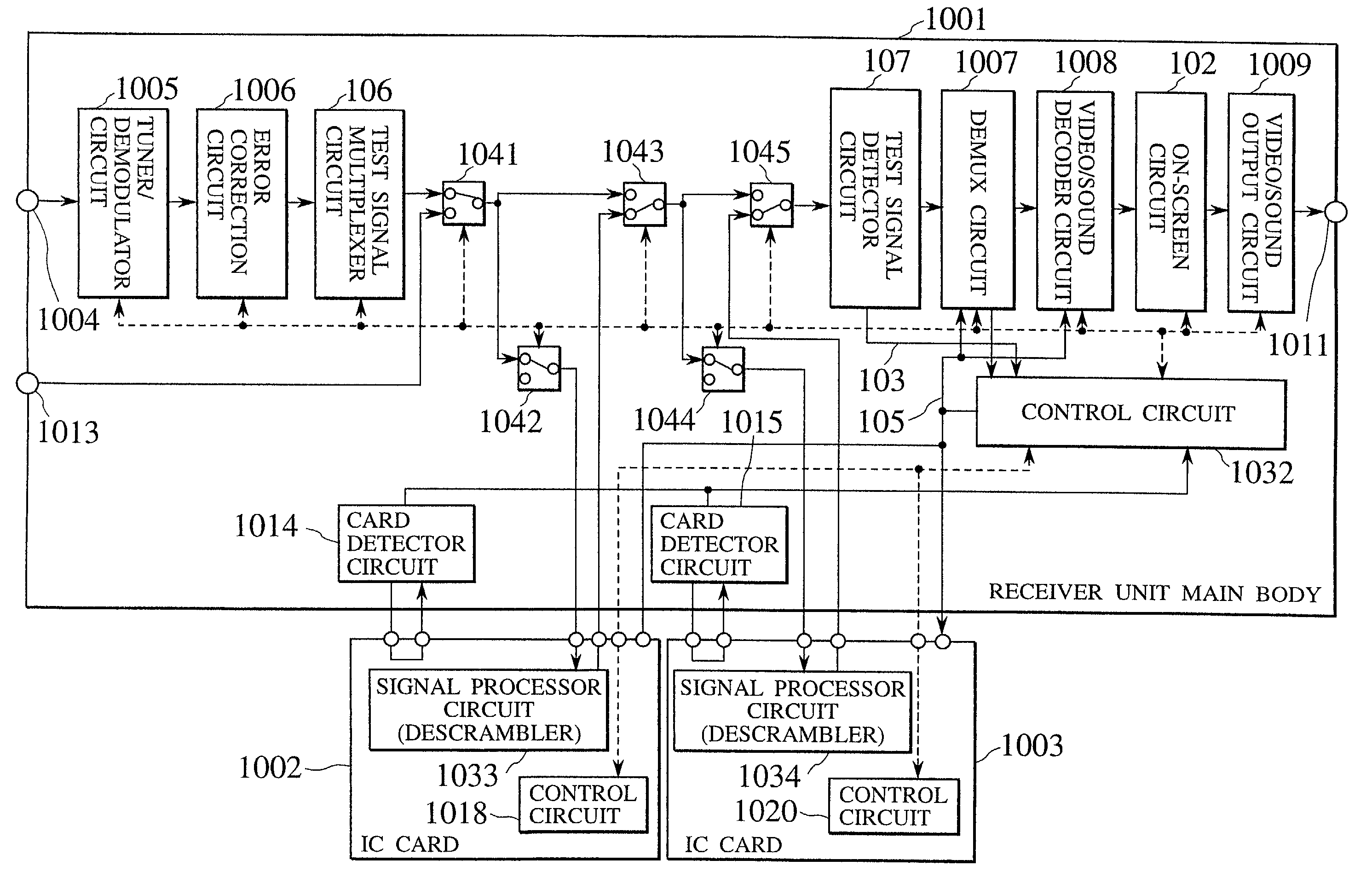
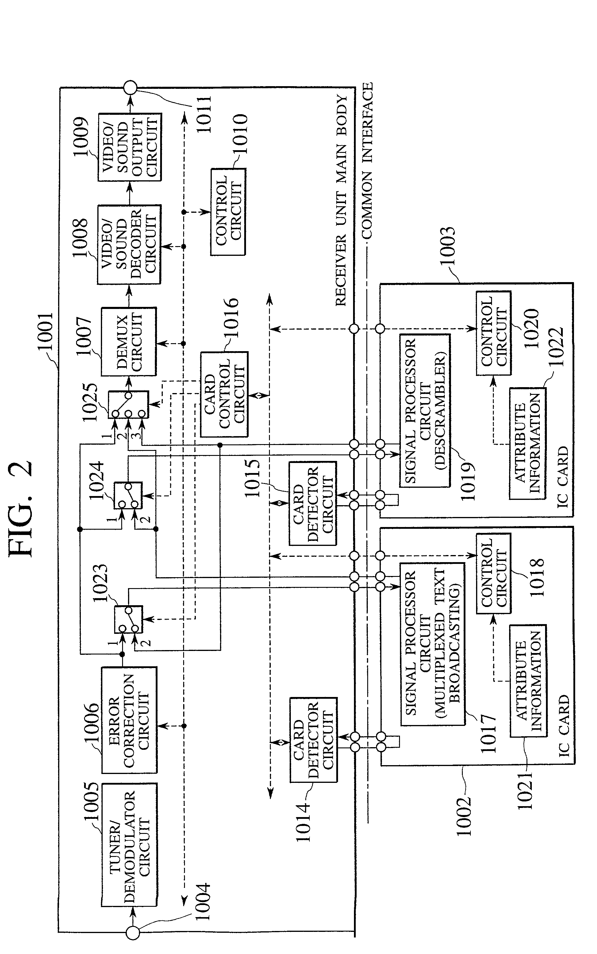
[0103]FIG. 2 is a block circuit diagram showing a digital broadcasting receiver unit according to the present invention. In an example of FIG. 2, the case where two sheets of card modules are employed is shown. However, the digital broadcasting receiver unit is not limited to this example. Similarly, the digital broadcasting receiver unit may be extended to the case where three sheets or more of card modules are inserted.

[0104]The digital broadcasting receiver unit comprises a receiver unit main body 1001 and two sheets of card modules 1002, 1003. As an interface standard between the receiver unit main body 1001 and the card modules 1002, 1003, a common interface standard is employed.

[0105]The receiver unit main body 1001 includes an input terminal 1004 for receiving the broadcasting signals such as the satellite broadcasting, the CATV broadcasting, etc.; a tuner / demodulator circuit 1005 for receiving the broadcast over a desired channel; an error correction circuit 1006 for correct...

second embodiment

[0147]Features of the second embodiment are given as the following points. Specifically, the synchronizing signal detector circuit 101 for outputting a synchronizing signal detecting signal is provided at the preceding stage of the DEMUX circuit 1007. The video / sound decoder circuit 1008 outputs newly an error detecting signal 104 to the control circuit 1032. Further, the on-screen circuit 102 for multiplexing the display data such as characters, etc. is provided at the succeeding stage of the video / sound decoder circuit 1008. The control circuit 1032 performs the separation control of the defective card modules by executing the change-over control of the switches based on the synchronizing signal detecting signal 103 and the error detecting signal 104, and also resets the circuits connected succeedingly to the defective card module by outputting a RESET signal 105.

[0148]The broadcasting signal 201 in FIG. 10 shows a data format of the normal digital broadcasting signal which is emp...

fourth embodiment

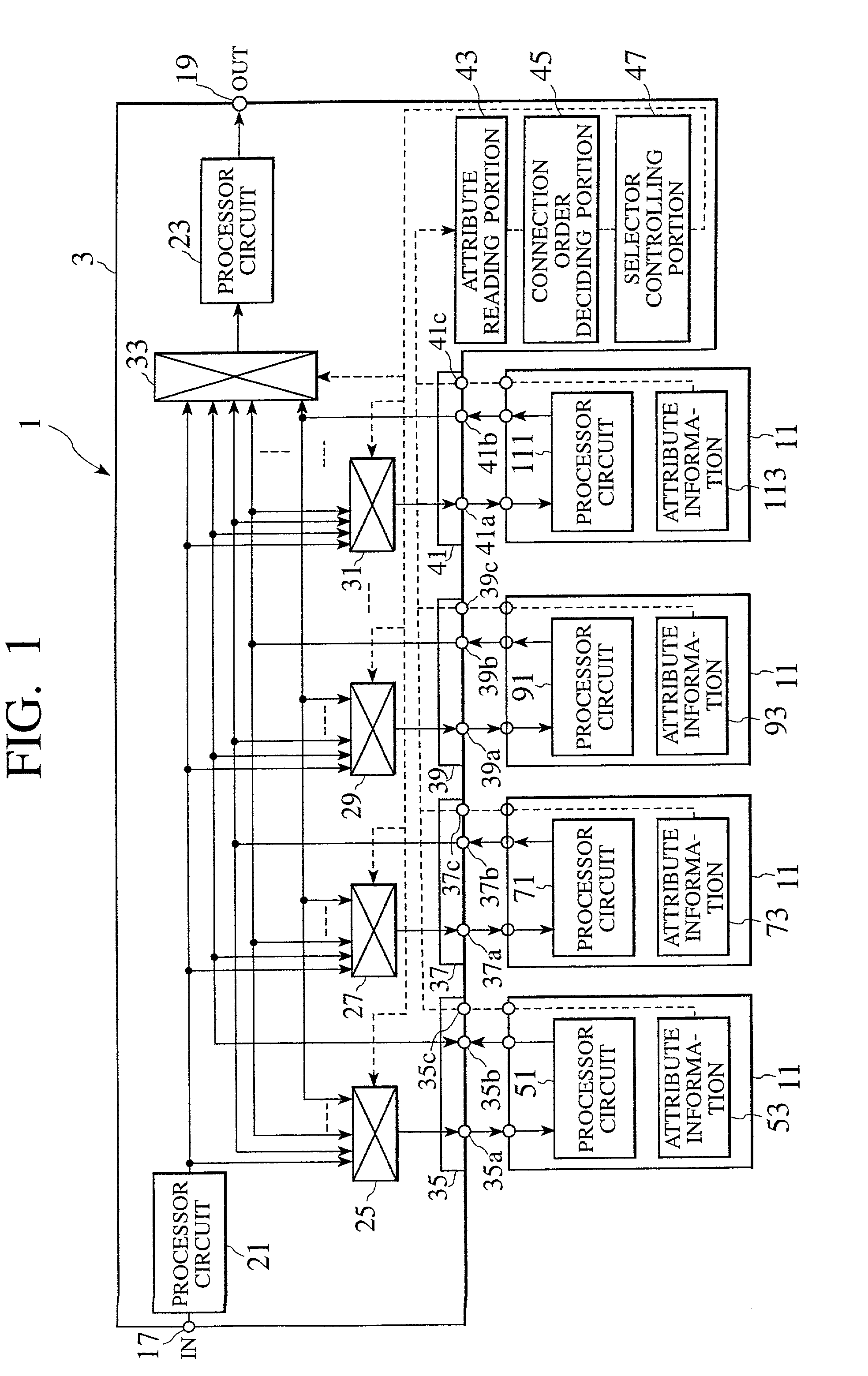
[0165] described above, the digital broadcasting receiver unit, in which one or more replaceable card modules are connected in the daisy-chain connection via the main body of the digital broadcasting receiver unit, with the excellent fault-tolerance can be provided. In other words, the digital broadcasting receiver unit can decide the failure of the card modules by detecting the synchronizing signal from the broadcasting signal outputs from the card modules or by detecting the decode error, and can continue the functions other than the defective cards by disconnecting the defective card modules from the system to switch the signals by the switches and to thus bypass the defective card modules or by resetting succeeding card modules and circuits subsequent to the defective card module.

[0166]In addition, if some card modules are defective, the large influence of them upon the remaining receiver system can be prevented as a whole.

[0167]Further, the user can know the failure contents by...


PUM


Abstract

An attribute reading portion (43) reads attribute information (53, 73, 93, 113) stored in a plurality of second units (5, 7, 9, 11). A connection order deciding portion (45) decides optimum order of a plurality of second units in a daisy-chain connection relative to a first unit (3) based on the read attribute information. A selector controlling portion (47) controls selectors (25, 27, 29, 31, 33) based on the decision. Also, according to another embodiment, when card modules (1002, 1003) are connected to a receiver unit main body, a daisy-chain connection of the card modules can be achieved by switches (1042, 1043, 1044, 1045). Then, a synchronizing signal detector circuit (101) detects a packet synchronizing signal in a digital broadcasting signal which is passed through the card modules. A video/sound decoder circuit (1008) decodes the digital broadcasting signal. In case an error is generated in each circuit (101, 1008), a control circuit (1032) disconnects the defective card module from the daisy-chain connection.

Description

TECHNICAL FIELD[0001]The present invention relates to a digital information receiver unit for receiving and watching the digital broadcasting such as the satellite broadcasting, the cable television (abbreviated as “CATV” hereinafter) broadcasting, etc. and, more particularly, improvement in interfacing between a unit and a receiver unit main body to / from which a card module for carrying out signal processing such as descrambling process of the chargeable broadcasting, etc. can be attached / detached.BACKGROUND ART[0002]In recent years, a plurality of enterprises for providing the digital satellite broadcasting service have been launched and thus such inconvenience is caused that different receiving units must be established according to individual enterprises. In order to overcome this inconvenience, common use of respective receiver units is being investigated currently while corresponding to scrambling operations in respective broadcasting stations.[0003]For instance, there is a DV...

Claims


Application Information

Patent Timeline
Patent Type & Authority Patents(United States)
IPC IPC(8): G06F13/40H04N5/00H04N5/44H04N7/16
CPCG06F13/4068H04N5/4401H04N7/163H04N21/4181H04N21/43607H04N21/4623H04N21/426
Inventor MACHIDA, HIROSHIYOSHIDA, OSAMU
Owner KK TOSHIBA
Why Eureka
Try Eureka