Knockout punch with pilot hole locator
a pilot hole locator and knockout punch technology, applied in metal-working equipment, metal-working equipment, manufacturing tools, etc., can solve the problems of poor positioning of the hole to be created, low punching force of the knockout punch, and inability to provide locating means for the prior art knockout punch. achieve the effect of improving the alignment of the punch
- Summary
- Abstract
- Description
- Claims
- Application Information
AI Technical Summary
Benefits of technology
Problems solved by technology
Method used
Image
Examples
first embodiment
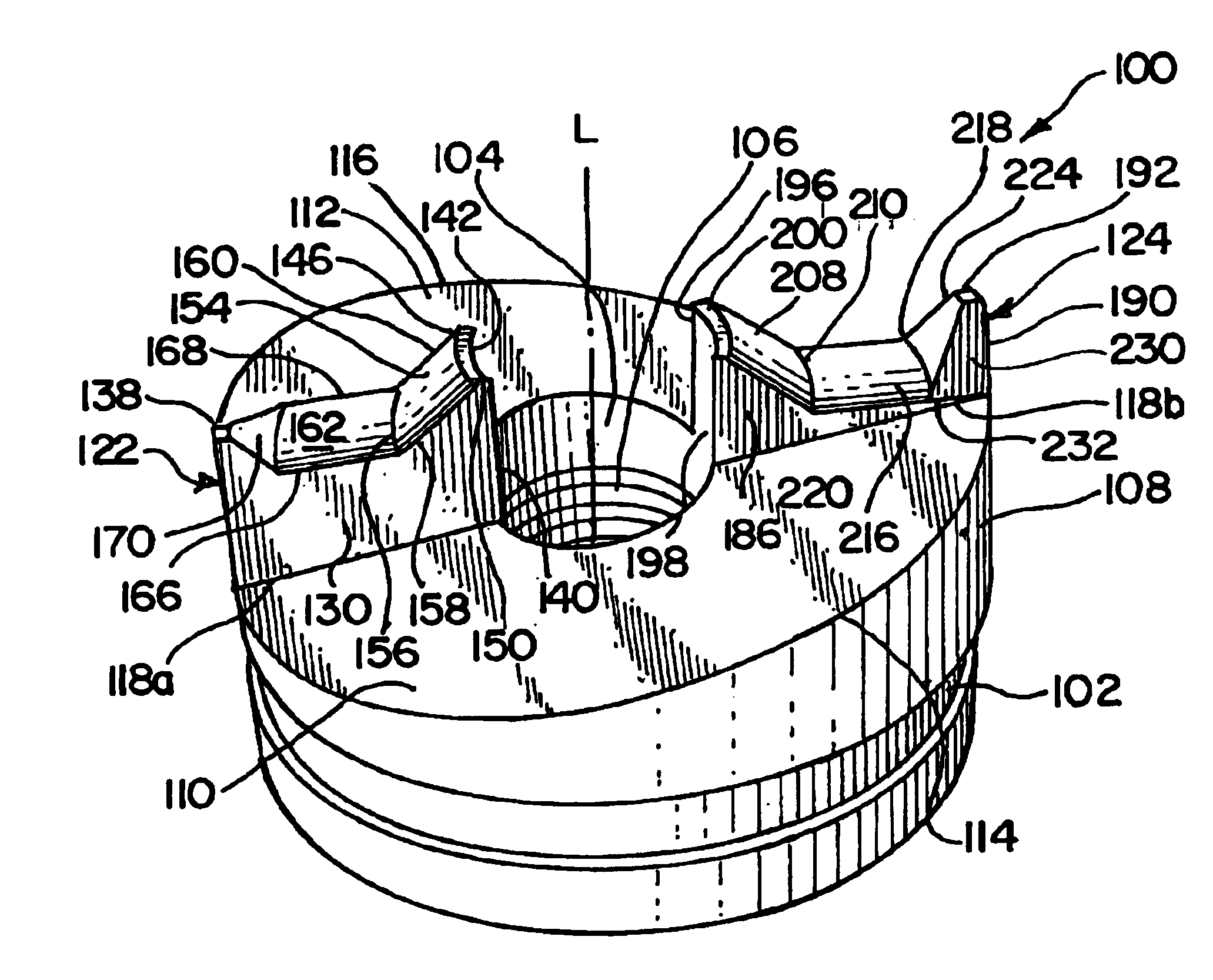
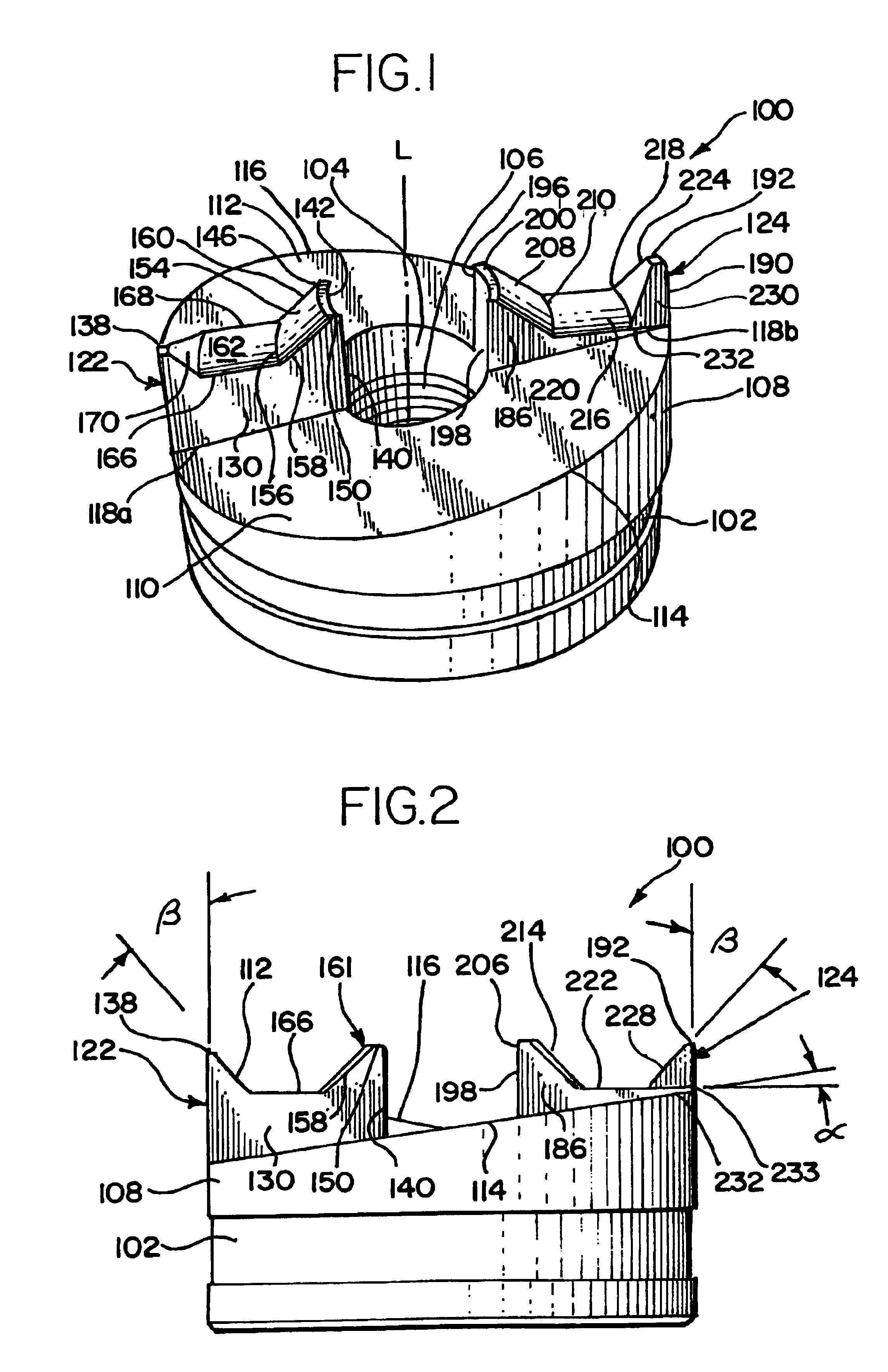
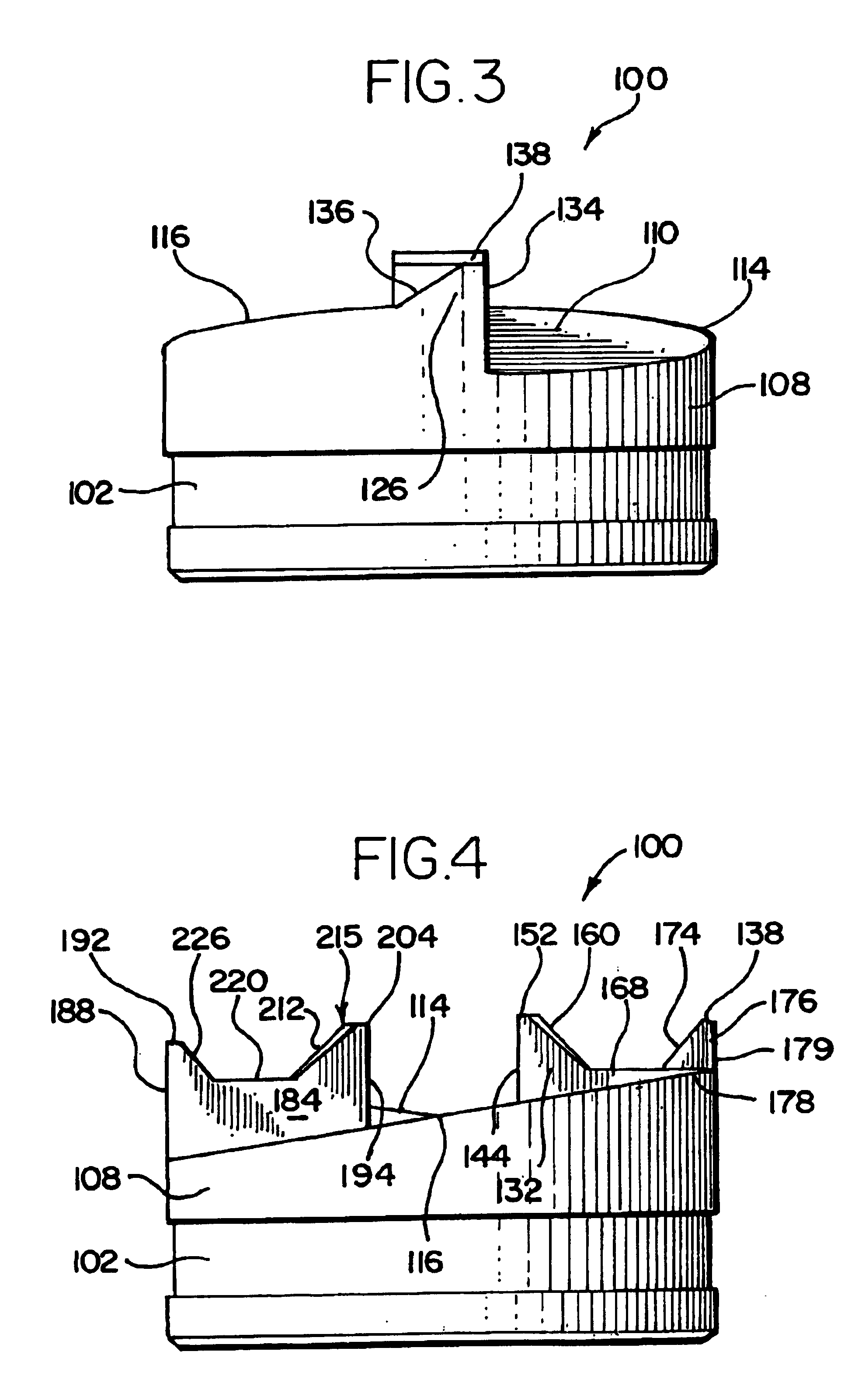
[0036]Attention is now directed to the punch 100 shown in FIGS. 1-5. The punch 100 includes a generally cylindrical punch body 102 and a punch face 108 having a passageway 104 extending axially therethrough. A wall 106 of the passageway 104 is typically threaded and threadably receives a threaded end of the draw stud in a conventional fashion. The working face 108 has a novel arrangement of inclined surfaces and associated cutting edges and surfaces for centering the punch 100, draw stud and die, which will be referred to collectively as the punch assembly, with the pilot hole, punching through the workpiece, and splitting apart of a slug to be removed from the workpiece.
[0037]The working face 108 includes a pair of inclined planar surfaces 110, 112 on opposite sides of a line D, see FIG. 5, which corresponds to the diameter of the working face 108. The inclined planar surfaces 110, 112 slope upwardly from the punch body 102 in opposite directions at an angle α. The inclined planar ...
fourth embodiment
[0070]Attention is now directed to the punch 700 shown in FIGS. 8-12. The punch 700 includes a generally cylindrical punch body 702 and a working face 708 having a passageway 704 extending axially therethrough. A wall 705 of the passageway is typically threaded and threadedly receives a threaded end of the draw stud in conventional fashion. The working face 708 has an arrangement of inclined surfaces and associated cutting edges. An insert 840 extends from the working face 708 and is permanently fastened into a counterbore 709 of the passageway 704 and is used for centering the punch 700, draw stud and die with the pilot hole prior to the punch 700 punching through the workpiece.
[0071]The working face 708 includes a pair of inclined planar surfaces 710, 712 on opposite sides of line D, which corresponds to the diameter of the working face 708. The inclined planar surfaces 710, 712 are generally crescent-shaped such that outer circumferential edges 714, 716 of the inclined planar sur...
PUM
 Abstract
Description
Claims
Application Information
 - R&D Engineer
- R&D Manager
- IP Professional
- Industry Leading Data Capabilities
- Powerful AI technology
- Patent DNA Extraction
Browse by: Latest US Patents, China's latest patents, Technical Efficacy Thesaurus, Application Domain, Technology Topic, Popular Technical Reports.
© 2024 PatSnap. All rights reserved.Legal|Privacy policy|Modern Slavery Act Transparency Statement|Sitemap|About US| Contact US: help@patsnap.com


