Combustion-engined setting tool

a technology of combustion engine and setting tool, which is applied in the direction of manufacturing tools, stapling tools, nailing tools, etc., can solve the problems of unfavorable combustion of air-fuel mixture, unfavorable pressure and temperature fluctuations, and slow setting process, so as to achieve the effect of simplifying manufacturing

Inactive Publication Date: 2005-12-13
HILTI AG
View PDF8 Cites 13 Cited by
  • Summary
  • Abstract
  • Description
  • Claims
  • Application Information

AI Technical Summary

Benefits of technology

[0012]The storage chamber has no communication with the environment and is filled with fuel, through the electronically controlled valve, before the setting tool is pressed against a constructional component. Because the storage chamber is filled with fuel before the tool is pressed against a constructional component, rapidly following one another, setting processes can take place. Advantageously, the inventive setting tool includes mechanical actuating means that provides for connection of the storage chamber with the combustion chamber in response to the setting tool being pressed against a constructional component. Upon the connection of the storage chamber with the combustion chamber, a precisely metered volume of fuel is fed into the combustion chamber. In this way, together with an increased output, a precise metering of fuel becomes possible. The electronically controlled valve enables a precise metering of fuel in its liquid phase. In the storage chamber, preferably, the fuel is stored in a gaseous phase.
[0015]Advantageously, a check valve is arranged between the storage chamber and the combustion chamber. The check valve is biased to its closed position and opens in response to a delivery displacement of the piston as a result of pressure build-up in the storage chamber. The check valve insures that the fuel would not flow prematurely into the combustion chamber, and no blow-back occurs when the mixture in the combustion chamber is ignited.
[0017]The shuttle valve is displaced from the first switching position to the second switching position in response to displacement of the mechanical actuating means from its initial position that corresponds to the initial position of the setting tool in which the storage chamber is disconnected from the combustion chamber and the electronically controlled valve is connected with the storage chamber, to its actuated position corresponding to a press-on position of the setting tool in which the storage chamber is disconnected from the electronically controlled valve and is connected with the combustion chamber. The shuttle valve is displaced from the second switching position to the first switching position in response to the displacement of the mechanical actuating means to its initial position upon lifting of the setting tool off a constructional component. The provision of the shuttle valve simplifies manufacturing of the setting tool in which the fuel flows from the storage chamber into the combustion chamber as a result of pressure existing in the storage chamber.
[0018]Advantageously, a check valve is provided in the fuel guide between the shuttle valve and the combustion chamber. The check valves open, against a biasing force, by pressure in the storage chamber. The check valve prevents a blowback when the mixture is ignited in the combustion chamber.
[0020]Advantageously, the electronically controlled valve is formed as a solenoid valve. The use of the solenoid valve insures that the valve exactly follows the control command of the control unit and also provides for a cost-effective construction of the setting tool.
[0022]The microprocessor insures a quick processing of the input data and requires a reduced constructional space.

Problems solved by technology

Generally, with use of fuel, there exists a problem of admixing, for each operational cycle, a proper amount of air or oxygen, which is used as oxidation means, to the fuel.
In particular, air, when taken from a surrounding environment, is subjected to pressure and temperature fluctuations which unfavorably influence the combustion of the air-fuel mixture, in particular when the fuel content in the mixture is too large or too small.
The drawback of this tool consists in that the process of filling the combustion chamber starts only after the tool has been pressed against a constructional components into which a fastening element is to be driven, and the switch is actuated.
This leads, in particular at low environmental temperatures, to a noticeable increase of the time period during which the combustion chamber is filled with fuel, which slows the setting process.
The drawback of the setting tool of DE 42 43 617 A1 consists in increased fuel losses.

Method used


Image

  • Combustion-engined setting tool
  • Combustion-engined setting tool
  • Combustion-engined setting tool

Examples


Embodiment Construction

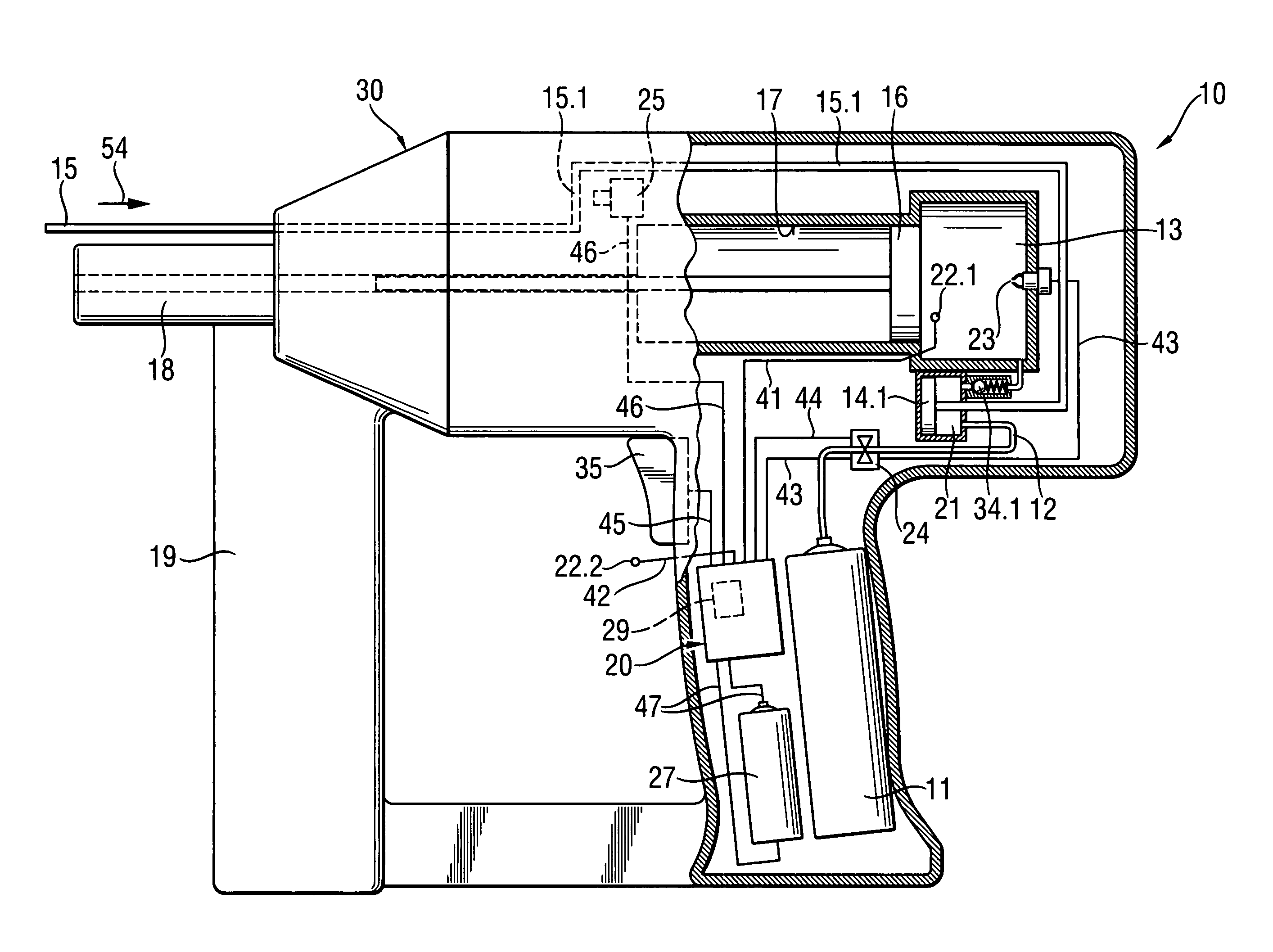
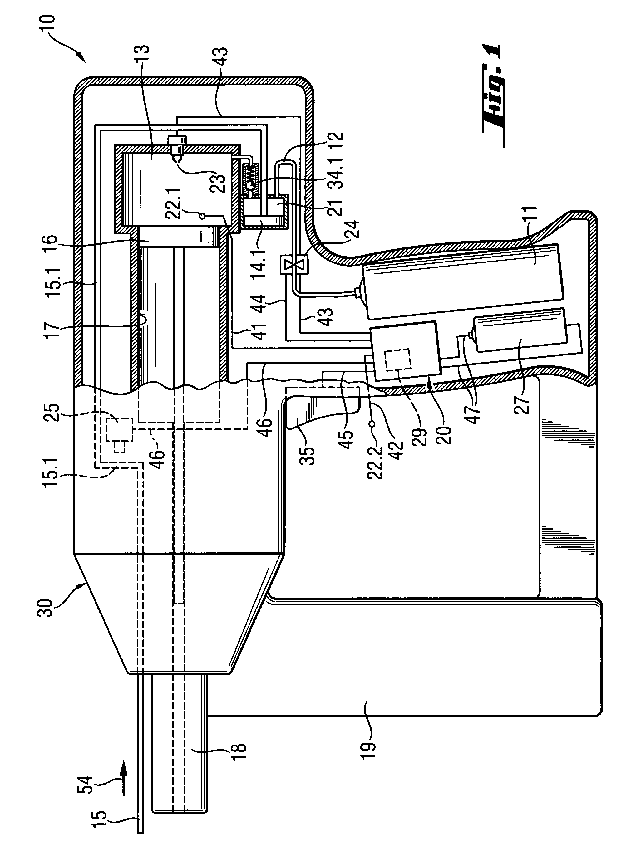
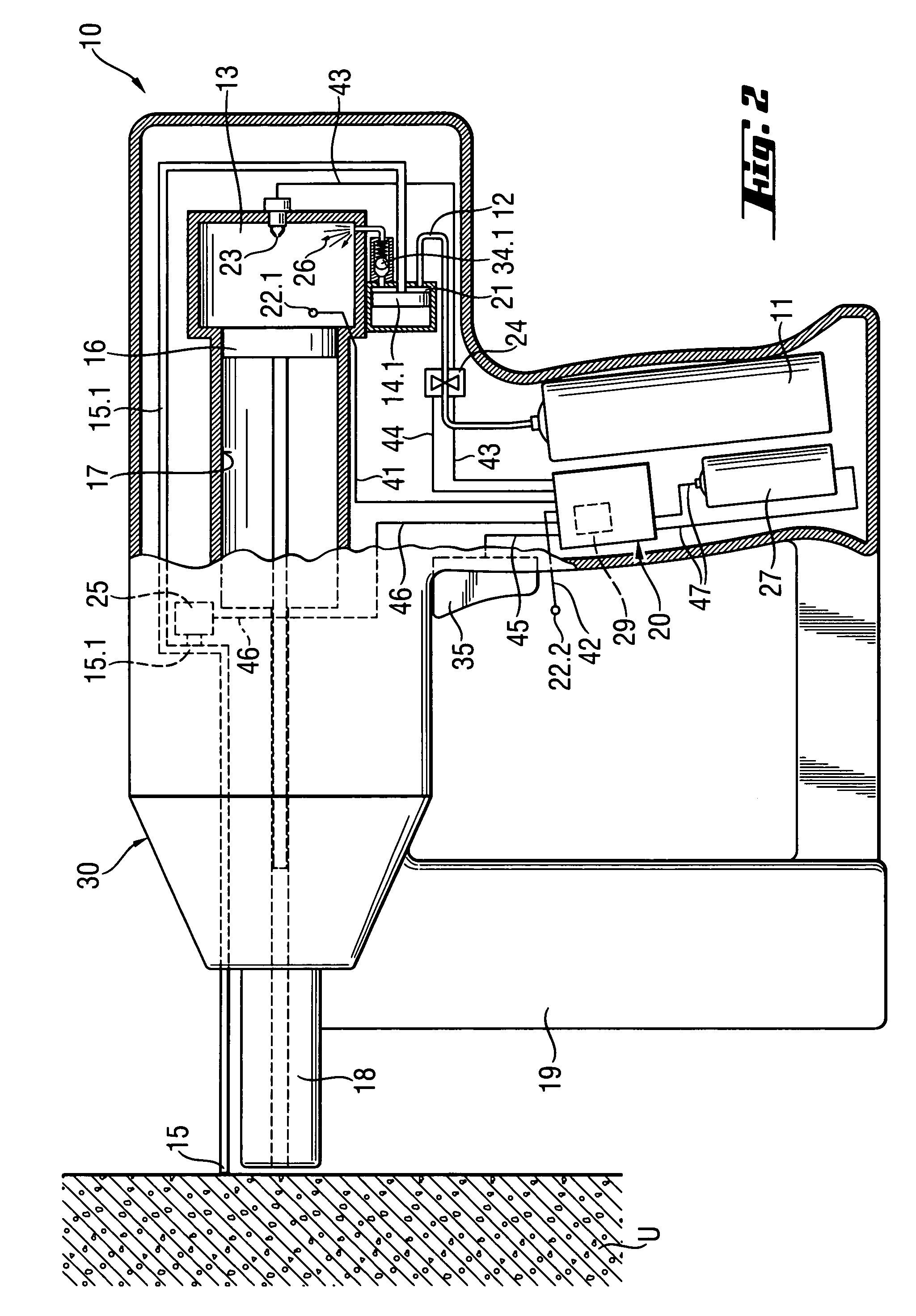
[0030]A setting tool 10 according to the present invention, a first embodiment of which is shown in FIGS. 1–4, is operated with a fuel gas. The setting tool 10, which is shown in FIG. 1 in its initial or off position, has a housing 30 in which a setting mechanism is located. The setting mechanism is used for driving a fastening element such as, e.g., a nail, a bolt, or the like, in a constructional component (not shown in FIG. 1) when the setting tool 10 is pressed against the constructional component and is actuated.

[0031]The setting mechanism includes, among others, a combustion chamber 13, a piston guide 17 in which a drive piston 16 is displaceably arranged, and a bolt guide 18 for a fastening element and in which the fastening element is displaceable by a forward movable, setting direction end of the drive piston 16 to be driven in the constructional component. Fastening elements are usually stored, e.g., in a magazine 19 attachable to the setting tool 10.

[0032]In the embodimen...


PUM


Abstract

The present invention relates to a combustion-engined setting tool for driving fastening elements, such as nails, bolts, pins in a constructional component, with a fuel guide (12) extending from a fuel source (11) to a combustion chamber (13) and with at least on electronically controlled valve (24) which is arranged in the fuel guide (12) between the fuel source (11) and the combustion chamber (13), and with a control unit (20), including at least one actuation means (25) with which the valve (24) is opened for a predetermined time period. For improving, it is proposed to arranged in the fuel guide (12) a storage chamber (21) between the electronically controlled valve (24) and the combustion chamber (13). The storage chamber becomes filled with fuel through the electronically controlled valve already before the setting tool is pressed against a constructional component, enabling rapid, following one after another, setting processes.

Description

BACKGROUND OF THE INVENTION[0001]1. Field of the Invention[0002]The present invention relates to a combustion-engined setting tool for driving fastening elements, primarily, in constructional components and including a fuel source, a combustion chamber, a fuel guide connecting the fuel source with the combustion chamber, at least one electronically controlled valve arranged in the fuel guide between the fuel source and the combustion chamber, and a control unit for opening the electronically control valve for a predetermined, by the control unit, time period.[0003]2. Description of the Prior Art[0004]Setting tools of the type described above operate on gaseous or liquid fuels which are combusted in the combustion chamber, driving the setting piston with which fastening elements are driven in.[0005]Generally, with use of fuel, there exists a problem of admixing, for each operational cycle, a proper amount of air or oxygen, which is used as oxidation means, to the fuel. In particular,...

Claims


Application Information

Patent Timeline
Patent Type & Authority Patents(United States)
IPC IPC(8): B25C1/08
CPCB25C1/008B25C1/08
Inventor SCHIESTL, ULRICHGSCHWEND, HANSHERTLEIN, PETERROSENBAUM, ULRICHWOLF, IWAN
Owner HILTI AG
Why Eureka
Try Eureka