Coating chamber and templates to produce decorative mouldings

a technology of decorative mouldings and templates, applied in the construction industry, can solve the problems of inability to rationalize standards, inability to provide templates that are adjustable, and high cost of methods

Inactive Publication Date: 2005-12-13
RAPONE SANTO P
View PDF3 Cites 7 Cited by
  • Summary
  • Abstract
  • Description
  • Claims
  • Application Information

AI Technical Summary

Benefits of technology

[0021]Adjusting the input template vertically to minimize the space between the top of the core and the template opening.
[0024]Adjusting side hinged plates internal to the coating chamber to funnel the coating material to the sides of the core, thus eliminating dead space in the corners of the coating chamber where the coating material would otherwise stagnate.
[0035]Means of providing easy cleanout of the said coating chamber.

Problems solved by technology

This method is very costly, in terms of labour and space.
So far there has not been any manufacturer to offer a rationalized standard, off the shelf, range of templates or coating chamber / hopper to accommodate such a selection.
No manufacturer has been able to provide templates that are adjustable to allow for the inevitable variation of the pre-formed core sizes.
While this method and apparatus does provide a coating on the decorative surface of the workpiece, in practise it can be very troublesome.
If the cores are not tightly placed end to end with each other as they pass through the coating chamber, the coating material leaks on to the conveyor belts and rail.
The leaked material can accumulate as lumps on the belts and impart an uneven finish on the workpiece.
Furthermore, as the last core passes through the coating chamber, all the excess material falls onto the rail and spiked belts thus requiring a meticulous cleanup.
Additionally, the apparatus disclosed in Canadian patent 2,229,933 published Aug. 19, 1999 is extremely limited in its application in coating decorative inside corner mouldings.
Also, an undesirable channel or dovetail is required on the underside of the core.
Furthermore, because the ends of the coating chamber are angled, the templates are not easily produced because of the complicated rendering of the resulting perpendicular section required on the workpiece.
Also, no method is disclosed to adjust the coating thickness other than the fixed sizes of the templates.
While this apparatus does provide a coating on the decorative surface of the workpiece, it is also troublesome and limited in its application.
Firstly, if the cores are not tightly butted up against each other, end to end, the coating material leaks on to the tabletop, accumulates and affects the thickness of the coating.
Holding the cores against the tabletop as they pass through the coating chamber creates friction that makes the cores harder to drive through the coating chamber.
Slipping can occur which results in an uneven surface finish.
Pieces of the core are carried into the coating chamber and contaminate the mix.
The dies as illustrated in the patent with tapered openings having sharp inside corners are not easily achieved, except by hand grinding and filing, making them too costly.
Additionally, the apparatus does not allow for adjusting the coating thickness other than the fixed sizes of the templates.

Method used


Image

  • Coating chamber and templates to produce decorative mouldings
  • Coating chamber and templates to produce decorative mouldings
  • Coating chamber and templates to produce decorative mouldings

Examples


Embodiment Construction

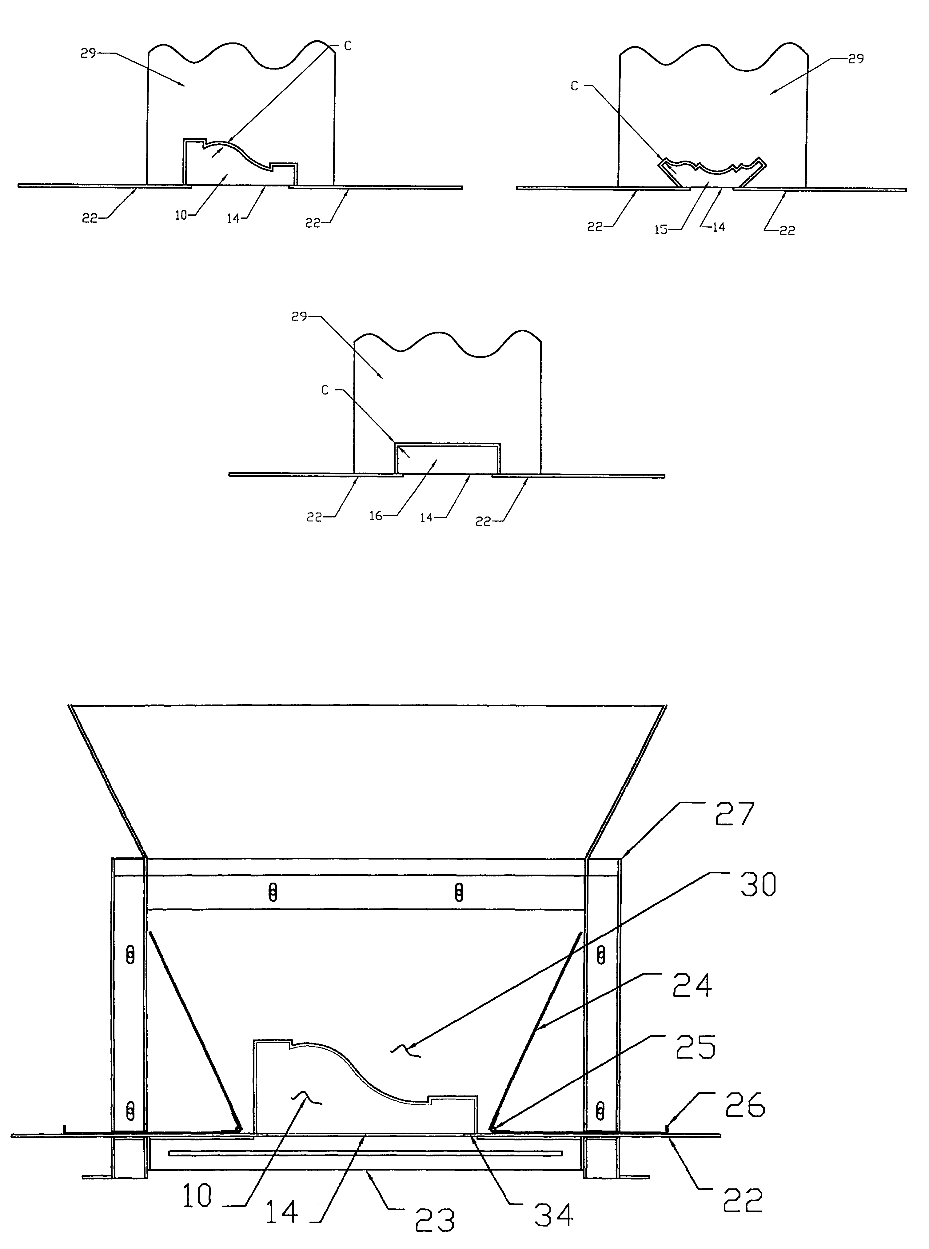
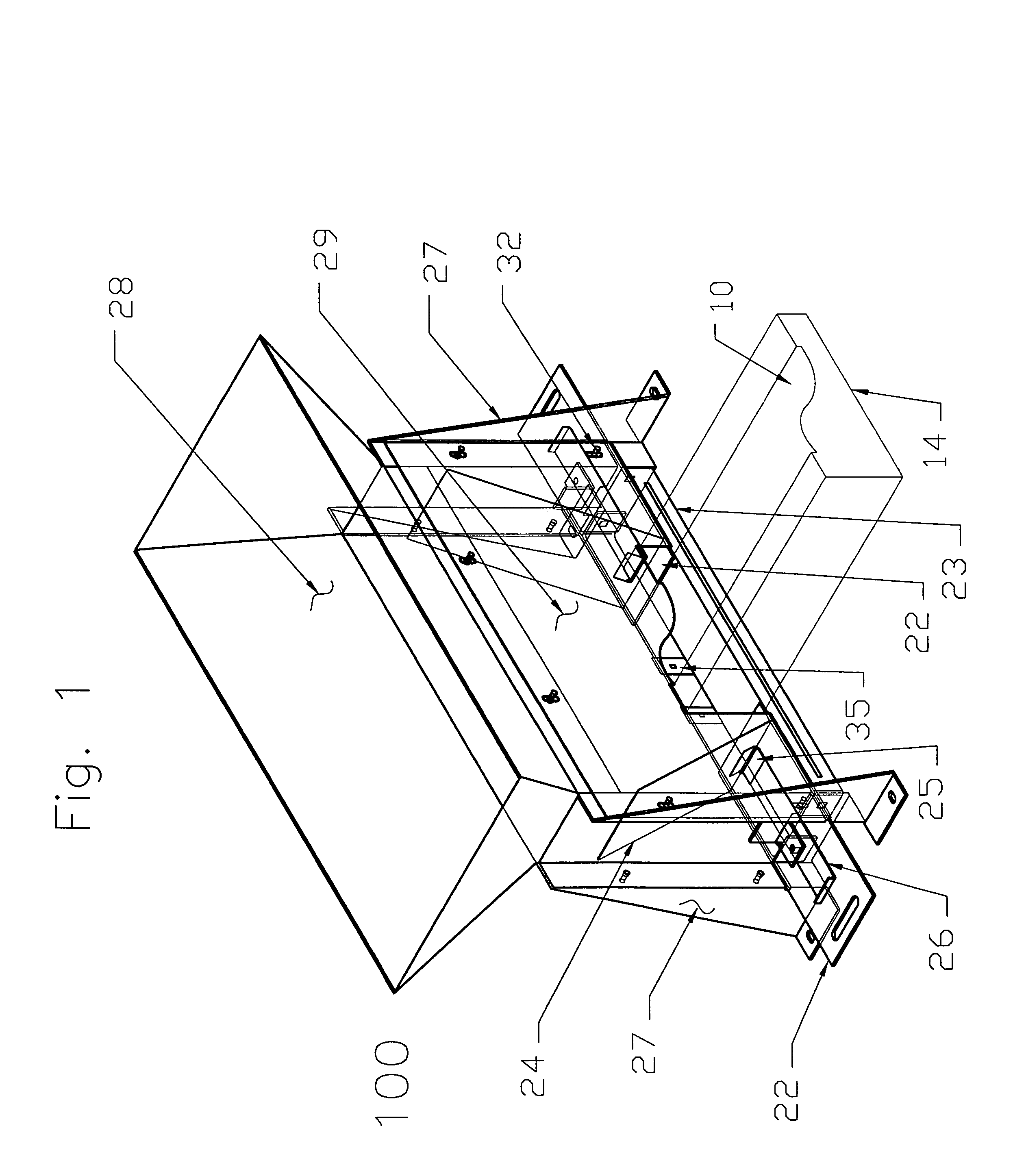
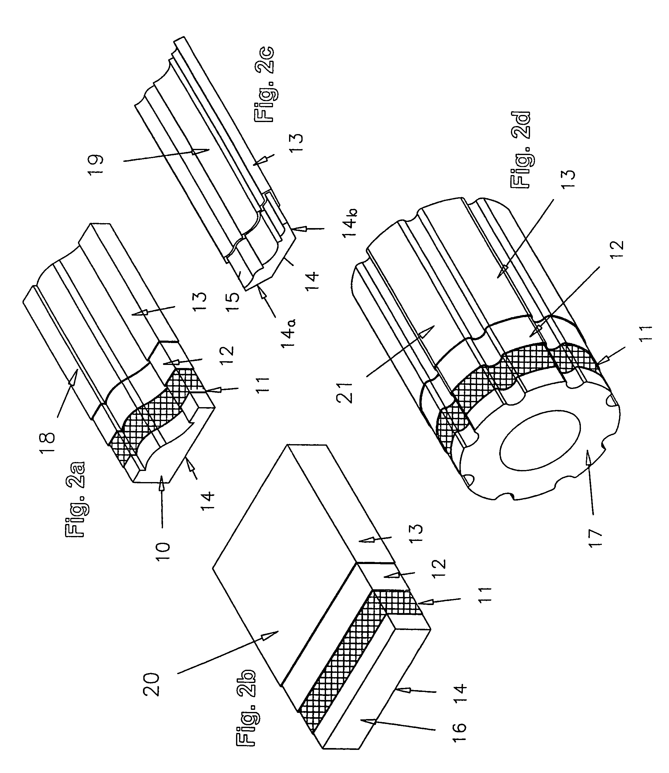
[0046]Referring to FIG. 1, there is illustrated apparatus 100 of the present invention in which a decorative moulding is coated. The workpiece comprises a core 10 (see FIG. 2) having coated surface 13 (see FIG. 2) which is profiled in cross-section, but elongated and consistent along its entire length. A mesh 11 (see FIG. 2) covers the surface 13 (see FIG. 2) before coating the workpiece and may overlap the sides to fold under on the surface 14 (see FIG. 2). The mesh acts as reinforcement to the workpiece but may be absent in mesh-less systems or advanced coatings with an inherent fibrous matrix.

[0047]The workpiece 18 is a decorative moulding designed to be mounted on an exterior wall by cementing it in place via bottom surface 14.

[0048]Workpiece 19 is an interior inside corner moulding and is attached by cementing surfaces 14a and 14b to a wall section.

[0049]Workpiece 20 is a wall panel.

[0050]Workpiece 21 is a column, which is produced by cementing together two halves after being c...


PUM

PropertyMeasurementUnit
sizesaaaaaaaaaa
surface profileaaaaaaaaaa
movementaaaaaaaaaa

Abstract

A method and apparatus to impart a coating layer on the surface of decorative mouldings that are widely used in the externally insulated finishing systems (EIFS) in the construction industry. The method is a sequence of mechanically advancing a core, constructed from pre-formed expanded polystyrene (EPS, in a straight horizontal plane through a coating chamber / hopper with templates conforming to the desired decorative profile. The apparatus is a rectangular box with a funneled opening at the top with adjustable internal plates to direct the material from the sides of the box toward the pre-formed core that is being coated. Two plates on the bottom of the box support the pre-formed core and are adjustable to leave an opening in the center so that excess material can fall through the bottom after coating the last core. The templates are designed to be interchangeable with other coating apparatus designed by the inventor to produce start strips, decorative mouldings, wall panel sections and columns commonly used in the construction industry.

Description

FIELD OF THE INVENTION[0001]This invention relates to the construction industry and is used to produce decorative mouldings comprised of pre-formed expanded polystyrene (hereinafter referred to as EPS) cores with a stucco / plaster / cement-like coating. The invention relates particularly to a method and apparatus for coating the cores with stucco / plaster / cement.BACKGROUND OF THE INVENTION[0002]The externally insulated finishing systems (hereinafter referred to as EIFS) construction basically consists of framing a building and covering the outside surface with a backboard that may be plywood, gypsum or cement board prior to attaching the exterior insulation and finish.[0003]The exterior insulation consists of EPS sheets mechanically or adhesively attached to the backboard. The EPS sheets are then covered with one or two layers of cloth mesh and a base coat of stucco.[0004]The base coat is either sprayed or trowelled on and finished smooth by hand with a float. A finish stucco material i...

Claims


Application Information

Patent Timeline
Patent Type & Authority Patents(United States)
IPC IPC(8): B05C3/12B05C3/18B05C5/02B05C11/02B28B1/32B28B19/00B29C44/56B29C67/00C09D1/06E04F13/00E04F19/04
CPCB05C3/12B05C3/18B28B19/0046B29C44/1285B29C44/56
Inventor SCHMIDT, DAVID
Owner RAPONE SANTO P
Why Eureka
Try Eureka