
Closed blood sampling system with isolated pressure monitoring

a blood sampling system and pressure monitoring technology, applied in the field of closed blood sampling systems, can solve the problems of unreliable blood chemistry measurement sample, degraded signal, and potential exposure of patients, and achieve the effects of improving pressure signal quality, reducing risk, and reducing risk

Active Publication Date: 2007-08-02
EDWARDS LIFESCIENCES CORP
View PDF95 Cites 7 Cited by
  • Summary
  • Abstract
  • Description
  • Claims
  • Application Information

AI Technical Summary

Benefits of technology

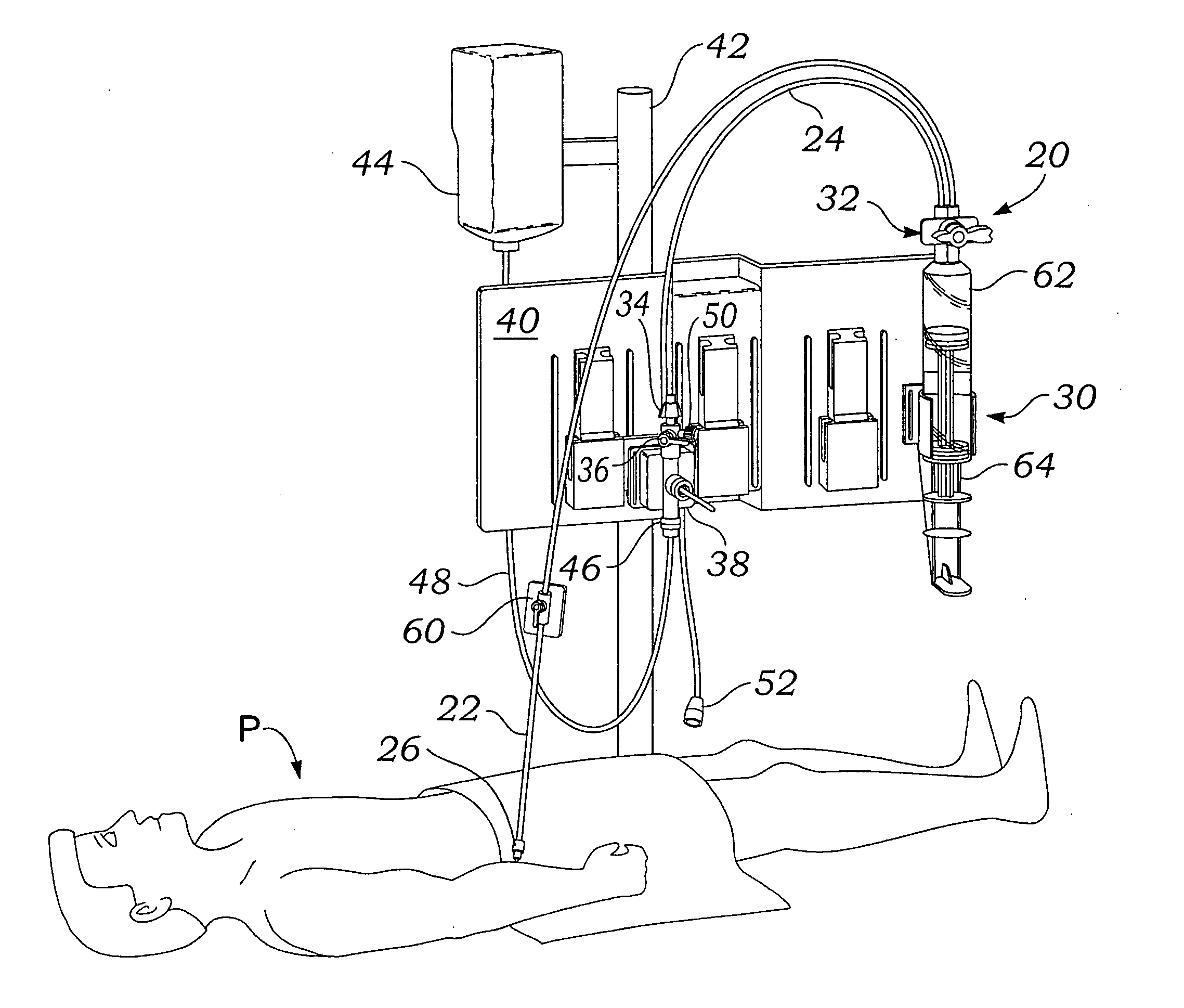
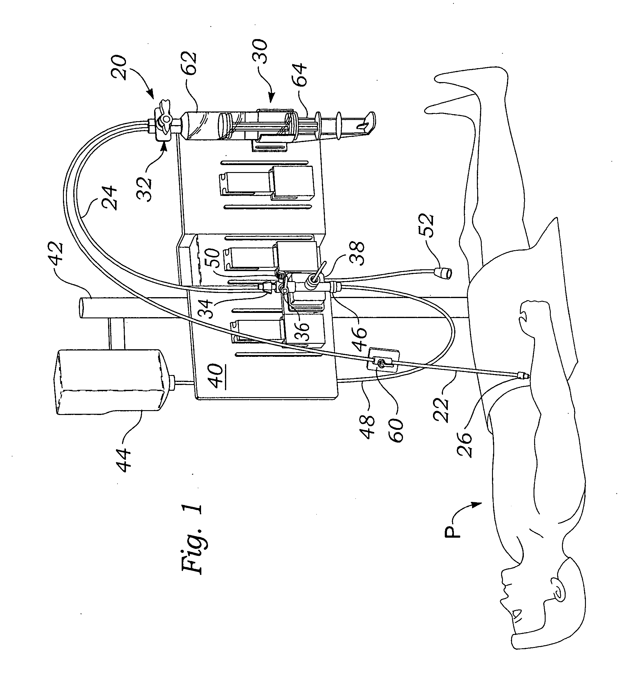
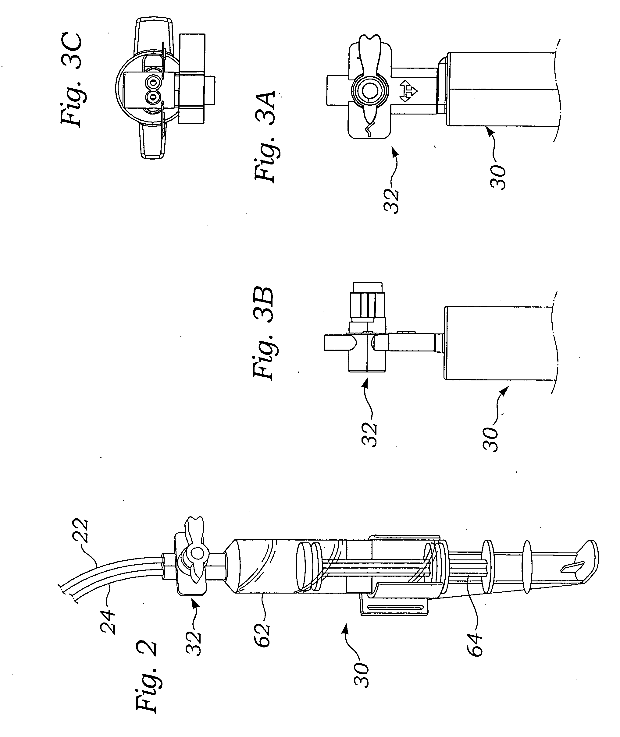
[0011] The present invention provides a fluid sampling system within a pressure monitoring line having a control valve that enables a clearance reservoir to be isolated from the pressure column when no samples are being taken. The control valve further permits complete flushing of the system with no dead spaces. Additionally, control valve desirably incorporates a sampling port therein capable of isolating the sampling port from the clearance reservoir. By isolating the clearance reservoir, the quality of the pressure signal is improved such that the sampling line can be lengthened for greater convenience in the intensive care or operating room.
[0013] a first position that provides open fluid communication from the proximal segment to the patient through the control valve so as to eliminate any dead spaces therein, wherein reduced pressure within the reservoir pulls fluid from the distal segment through the control valve and into the reservoir sufficient to draw fluid from the fluid system of the patient past the sampling port, and
[0015] Desirably, the valve member also has a third position that provides open fluid communication from the distal segment to the sampling port but prevents communication between the sampling port and both the reservoir and the proximal segment.
[0023] a third position that provides open fluid communication from the distal segment to the sampling port but prevents communication between the sampling port and both the reservoir and the proximal segment.
[0030] The method includes selecting the first position of the valve member to provide open fluid communication from the proximal segment to the distal segment via the control valve and the reservoir, and creating a reduced pressure within the reservoir such that fluid flows from the distal segment through the control valve into the reservoir sufficient to draw fluid from the fluid system of the patient past the sampling port. The method further includes selecting the second position of the valve member to provide open fluid communication from the proximal segment to the distal segment via the control valve while bypassing the reservoir, and monitoring the pressure sensed by the pressure transducer. Desirably, the valve member has a third position, and the method includes selecting the third position of the valve member to provide open fluid communication from the distal segment to the sampling port but prevent communication between the sampling port and both the reservoir and the proximal segment, and sampling fluid from the conduit line through the sampling port.
[0043] a third position that provides open fluid communication from the distal end of the conduit line through the control valve to the sampling port but prevents communication between the sampling port and the proximal end of the conduit line.

Problems solved by technology

Such frequent sampling injections potentially expose the patient to airborne bacteria and viruses which can enter the bloodstream through the opening made by the sharpened cannula.
This first sample potentially included some of the infusion fluid and thus would be an unreliable blood chemistry measurement sample.
However the limited amount of space available or the location of the anesthesiologist during a surgical procedure often necessitates a relatively long tubing line which degrades the signal.

Method used


Image

  • Closed blood sampling system with isolated pressure monitoring
  • Closed blood sampling system with isolated pressure monitoring
  • Closed blood sampling system with isolated pressure monitoring

Examples


Embodiment Construction

[0062] The present invention provides an improved closed blood sampling system in conjunction with pressure monitor. As mentioned above, continuous or periodic blood pressure monitoring is a common and extremely useful tool in the intensive care or operating room. However, it should be mentioned that the apparatuses and methods described herein could be utilized in conjunction with any fluid system of a patient which would benefit from pressure monitoring. For instance, intracranial pressures could be monitored and cerebrospinal fluid samples taken by placing the system described herein in fluid communication with an intraventricular catheter. Therefore, the appended claims cover the sampling and monitoring of any fluid system within a patient unless otherwise specified.

[0063] The present invention comprises an improved, closed, one-handed fluid sampling system especially useful for sampling blood in the operating room or critical care unit (CCU). The overall functioning of the sys...


PUM


Abstract

A closed blood sampling system within a pressure monitoring line having a control valve that enables a clearance reservoir to be isolated from the pressure column when no samples are being taken. The valve is a stopcock-like device that includes a rotating valve member and attached control handle with clear visible and tactile indicators for the mode of operation. The rotating valve member has a number of internal and circumferential channels for connecting or disconnecting select ports in the core of the valve. By isolating the clearance reservoir, the quality of the pressure signal is improved such that the sampling line can be lengthened for greater convenience in the intensive care or operating room. The valve may also incorporate a blunt cannula sampling site therewithin.

Description

RELATED APPLICATIONS [0001] The present application claims the benefit of priority under 35 U.S.C. §119(e) from provisional application No. 60 / 717,119, filed Sep. 13, 2005, and from provisional application No. 60 / 720,263, filed Sep. 21, 2005.FIELD OF THE INVENTION [0002] The present invention relates to blood sampling systems and, in particular, to closed blood sampling systems with a clearing reservoir and pressure monitoring. BACKGROUND OF THE INVENTION [0003] In a hospital setting there is always the need to monitor patient health through the evaluation of blood chemistry profile. The simplest method employed in the hospital is to use a syringe carrying a sharpened cannula at one end and insert that cannula into a vein or artery to extract a blood sample from the patient. Patients that are in the critical care units or the operating room sometimes require as many as twelve samples a day. Such frequent sampling injections potentially expose the patient to airborne bacteria and vir...

Claims


Application Information

Patent Timeline
Patent Type & Authority Applications(United States)
IPC IPC(8): A61B5/00A61F13/15
CPCA61B5/1427A61B5/0215A61B5/15003A61B5/150221A61B5/150236A61B5/150244A61B5/150816A61B5/150824A61B5/150992A61B5/1535
Inventor GORDON, MARKLIU, JOHNCOUCHMAN, SCOTTDRORI, HAGAY
Owner EDWARDS LIFESCIENCES CORP
Learn More