Multiband branch radiator antenna element

a radiator antenna and multi-band technology, applied in the field of wireless communication, can solve the problems of complex antenna feed network in such a dual-band configuration, complex or otherwise undesirable, and high and achieve the effect of reducing the cost of antenna feed cables

Inactive Publication Date: 2005-12-13
HONG KONG APPLIED SCI & TECH RES INST
View PDF5 Cites 94 Cited by
  • Summary
  • Abstract
  • Description
  • Claims
  • Application Information

AI Technical Summary

Benefits of technology

[0012]Embodiments of the present invention utilize one or more reflectors, such as to provide directivity and / or radiation pattern shaping. For example, embodiments of the present invention may utilize one or more radiating branches of a multi-band antenna element as a reflector for another one or more radiating branches of the multi-band antenna. Additionally or alternatively, ground plane surfaces may be utilized as reflectors according to embodiments of the invention.

Problems solved by technology

Moreover, patch antennas often require complicated manufacturing processes and / or assembly techniques in order to provide a useful antenna array.
Accordingly, a relatively large number of antenna elements are utilized and a relatively complex antenna configuration results.
Moreover, the antenna feed network in such a dual-band configuration may be complex or otherwise undesirable.
For example, separate low loss (and expensive) antenna feed cables may be required by each such interleaved antenna array.
However, frequency optimization often results in adjusting current paths and, in most cases, involves impedance matching of the required bands.
Such dual-band dipole elements can be relatively expensive and complicated to design and produce.
However, the use of such dual-band modes further complicates the design and manufacture of such elements.
Moreover, such antenna elements remain relatively large.
Accordingly the use of patch antenna elements may not be desirable in particular dual-band systems.

Method used


Image

  • Multiband branch radiator antenna element
  • Multiband branch radiator antenna element
  • Multiband branch radiator antenna element

Examples


Embodiment Construction

[0029]In understanding the concepts and advantages of embodiments of the present invention, a discussion of various prior art antenna element configurations is helpful. Accordingly, some detail with respect to prior art antenna configurations, such as information with respect to dipole antenna elements, is provided hereinbelow.

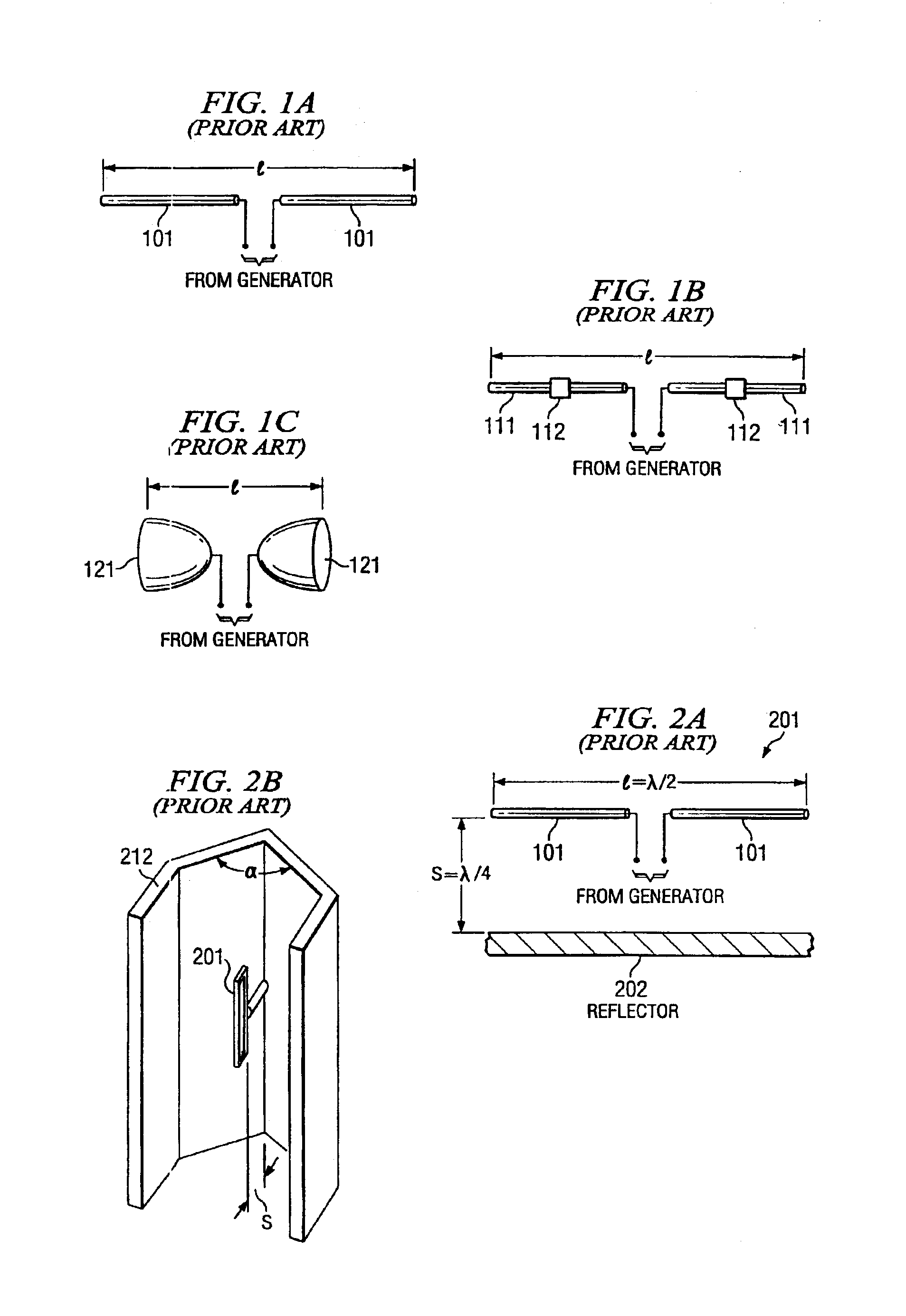
[0030]A dipole is formed by a pair of balanced transmission lines, opened-out into a twin colinear line (poles 101) as shown in FIG. 1A. Its radiation pattern, radiation resistance and directivity are critically dependent upon length (l). A widely accepted optimum length is the half-wave dipole configuration (l=½λ) with a fundamental radiation pattern resembling a doughnut shape. This is a result of sinusoidal current vanishing at end points of the dipole. In other words, the configuration is limited to a single resonant frequency with the fundamental radiation pattern, dictated by its physical resonant length l. Gain of such dipole antennas has been measured ...


PUM


Abstract

Disclosed are systems and methods which provide multi-band antenna elements using multiple radiating branches interconnected with a feed plate, thereby providing a multi-band antenna element having a single feed. Additionally or alternatively, a wide band antenna configuration is provided utilizing multiple radiating branches of a multi-band antenna element of the present invention. Embodiments utilize one or more reflectors, such as to provide directivity and/or radiation pattern shaping, including utilizing one or more radiating branches of a multi-band antenna element as a reflector for another one or more radiating branches of the multi-band antenna.

Description

TECHNICAL FIELD[0001]The invention relates generally to wireless communications and, more particularly, to multi-band antenna configurations.BACKGROUND OF THE INVENTION[0002]Various antenna element and antenna array configurations are utilized in wireless communications today. The dipole antenna, for example, is one of the most commonly encountered antenna configurations today. Their simplicity makes them relatively inexpensive and easy to build and deploy. As such, the dipole antenna is probably the most widely used form of antenna element in various mobile and base station installations.[0003]Generally speaking, a dipole antenna element gives only 2.13 dBi of gain. Accordingly, many current manufacturers of wireless systems will use a pair of dipoles, such that the gain increases to about 5 dBi. For example, an antenna array may be configured in which pairs of dipole antenna elements are disposed above a ground plane to provide a desired level of gain and a radiation pattern havin...

Claims


Application Information

Patent Timeline
Patent Type & Authority Patents(United States)
IPC IPC(8): H01Q5/00H01Q5/371H01Q5/48H01Q9/26
CPCH01Q9/26H01Q5/48H01Q5/371H01Q19/106
Inventor SONG, PETER CHUN TECKMURCH, ROSS DAVID
Owner HONG KONG APPLIED SCI & TECH RES INST
Why Eureka
Try Eureka