Method and system for providing a shared write driver

a write driver and write technology, applied in the field of memory systems, can solve the problems of increasing the load on the signal, consuming a large amount of die area of the write driver, and additional layout time, and achieve the effect of reducing disadvantages and problems

Inactive Publication Date: 2005-12-13
GLOBALFOUNDRIES INC
View PDF19 Cites 20 Cited by
  • Summary
  • Abstract
  • Description
  • Claims
  • Application Information

AI Technical Summary

Benefits of technology

[0005]In accordance with the present invention, a method and system for providing a write driver are provided that substantially eliminate or redu...

Problems solved by technology

Thus, the write drivers consume a large amount of die area.
In addition, this results in ...

Method used


Image

  • Method and system for providing a shared write driver
  • Method and system for providing a shared write driver
  • Method and system for providing a shared write driver

Examples


Embodiment Construction

[0023]FIGS. 1 through 10, discussed below, and the various embodiments used to describe the principles of the present invention in this patent document are by way of illustration only and should not be construed in any way to limit the scope of the invention. Those skilled in the art will understand that the principles of the present invention may be implemented in any suitably arranged memory system.

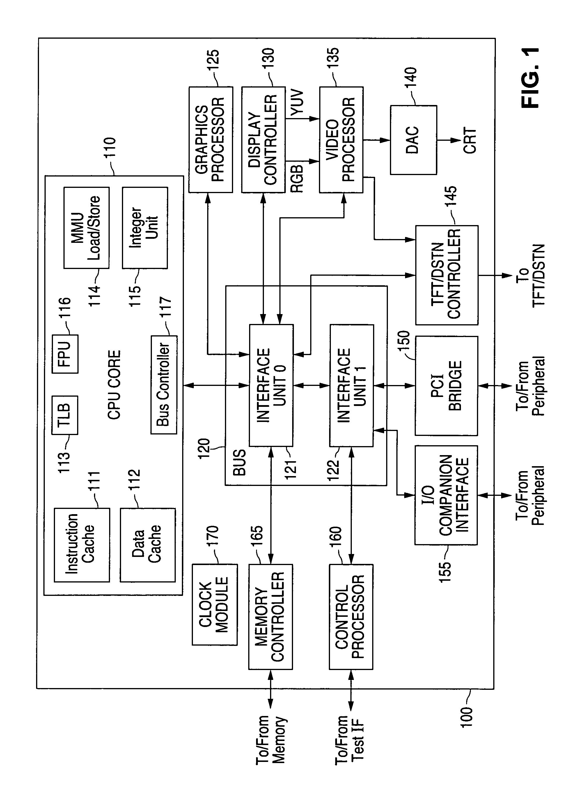
[0024]FIG. 1 is a block diagram illustrating a processing system 100 in accordance with one embodiment of the present invention. The processing system 100 is for illustration only. Other processing systems could be used without departing from the scope of this disclosure.

[0025]In the illustrated example, the processing system 100 includes a central processing unit (CPU) core 110. The CPU core 110 executes instructions, such as integer instructions and floating point instructions. For example, the CPU core 110 could execute instructions contained in an application executed by a host comp...


PUM


Abstract

A method for providing a shared write driver is provided. The method includes providing a write driver for a memory array. The memory array comprises a plurality of memory columns. The write driver is coupled to the plurality of memory columns.

Description

TECHNICAL FIELD OF THE INVENTION[0001]The present invention relates generally to memory systems and, more particularly, to a method and system for providing a shared write driver.BACKGROUND OF THE INVENTION[0002]Different types of memory are used in different types of applications, such as electronic applications, for both temporary and permanent storage. One type of memory commonly used is static random access memory (SRAM). SRAM memory cells provide relatively high speed, and CMOS SRAM memory cells use relatively low standby power and require no refresh cycle to maintain the data stored in the SRAM cells. For these reasons, SRAM memory systems are often used in portable applications.[0003]SRAM memory systems are typically provided in memory arrays that are arranged in rows and columns. Each SRAM memory cell may be identified by a combination of a particular row address with a particular column address. The row address has a corresponding wordline and the column address has a corre...

Claims


Application Information

Patent Timeline
IPC IPC(8): G11C8/00G11C11/419
CPCG11C11/419
Inventor LAPIDUS, PETER D.TO, YAT-LOONG
Owner GLOBALFOUNDRIES INC
Why Eureka
Try Eureka