X-ray generator and slip ring for a CT system

a technology of ct system and generator, which is applied in the field of diagnostic imaging system using computed tomography, can solve the problems of increasing the force placed on the retaining bracket, and affecting the accuracy of the x-ray generator

Inactive Publication Date: 2005-12-13
GENERAL ELECTRIC CO
View PDF11 Cites 82 Cited by
  • Summary
  • Abstract
  • Description
  • Claims
  • Application Information

AI Technical Summary

Problems solved by technology

For example, rotating at higher gantry speeds is problematic because the mass of the components on the rotating side as well as their associated rotational forces limit gantry speed.
Further, the size of the x-ray generator components in current CT systems have resulted in a cantilevered configuration out from the rotating base.
This cantilevered configuration adds a torque on mounting brackets used to secure the components as well as increases the forces placed on the retaining brackets.
All of which limit gantry rotational speed.

Method used


Image

  • X-ray generator and slip ring for a CT system
  • X-ray generator and slip ring for a CT system
  • X-ray generator and slip ring for a CT system

Examples


Embodiment Construction

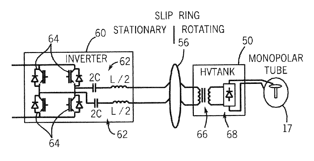
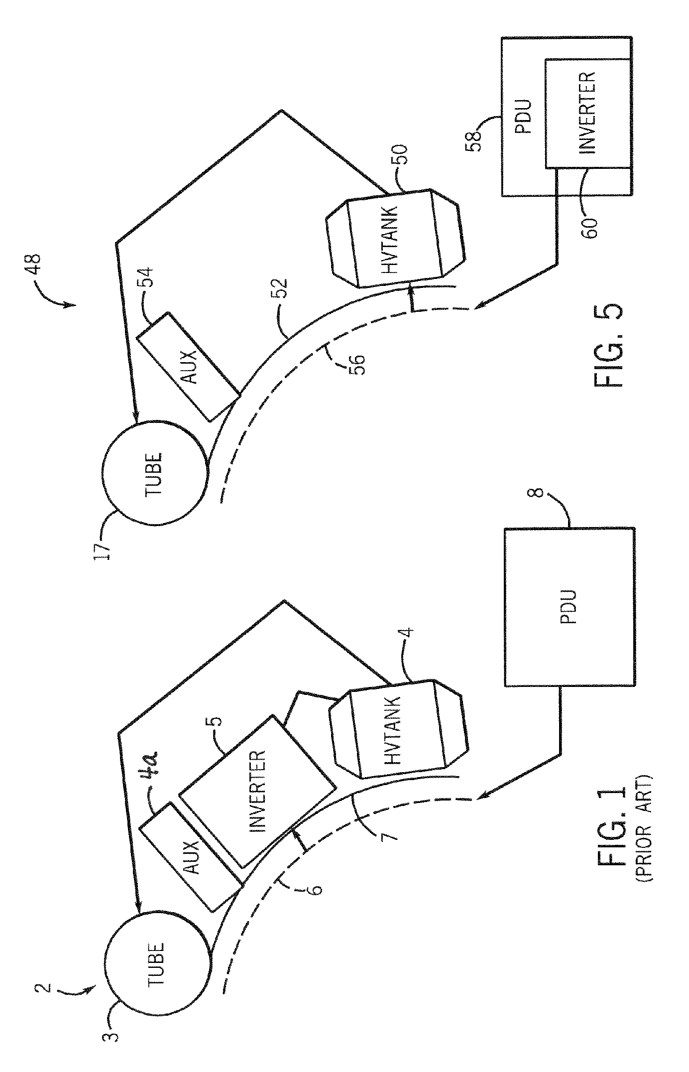
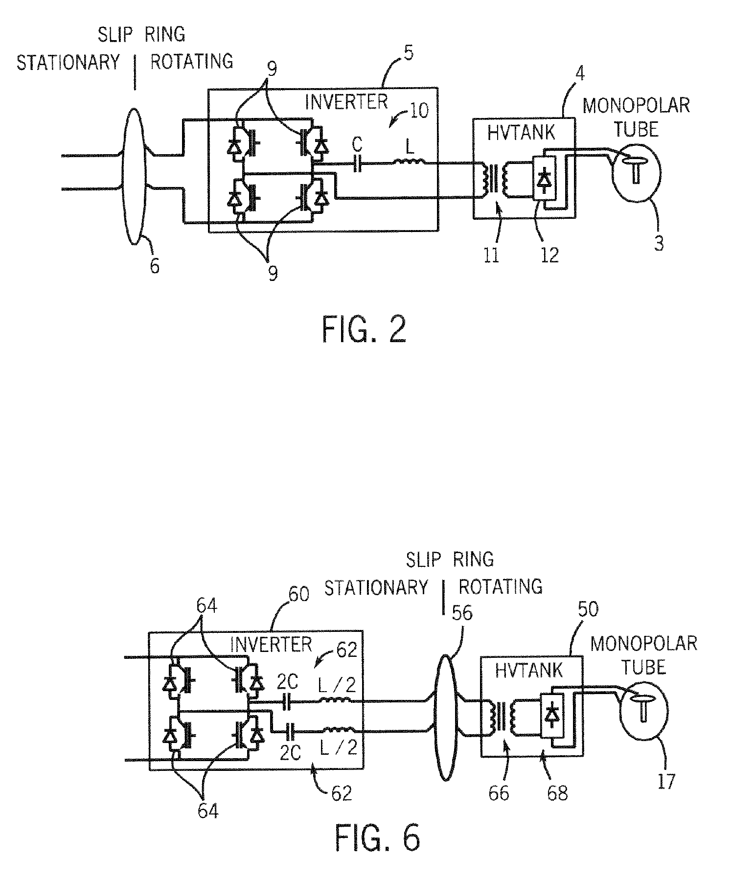
[0025]Referring to FIGS. 3 and 4, a computed tomography (CT) imaging system 14 is shown as including a rotatable gantry 15 representative of a “third generation” CT scanner. Gantry 15 is positioned in a gantry support 16 and has an x-ray tube 17 that projects a beam of x-rays 18 toward a detector array 19 on the opposite side of the gantry 15. Gantry 15 is designed to rotate and, as such, is defined as a rotating side whereas support 16 does not rotate and, as such, is defined as a stationary side. A slip ring (not shown) is positioned proximate to a rotating base (not shown) for transference of current to x-ray generator components that rotate during data acquisition. The rotating base is designed to support x-ray tube 17, a high voltage (HV) tank (not shown), and other auxiliary components (not shown) during rotation around a medical patient 22. As will be described in greater detail below, the slip ring is constructed to transfer power received from a stationary inverter (not sho...


PUM


Abstract

The present invention is directed to an apparatus for supplying power to a rotatable x-ray tube for generation of an x-ray beam for acquisition of CT data. The apparatus includes a slip ring to transfer power from a stationary inverter to a rotatable HV tank. The HV tank conditions the transferred power and creates a voltage potential across the x-ray tube for x-ray generation. The inverter has a single or pair of series resonant circuits connected either directly to the slip ring or indirectly through a transformer to limit frequency content and reduce common-mode component of the voltage and current waveforms carried by the slip ring as well as reduce power losses.

Description

BACKGROUND OF INVENTION[0001]The present invention relates generally to diagnostic imaging systems using computed tomography and, more particularly, to an x-ray generator and slip ring for a CT system such that a stationary inverter supplies power to the slip ring for transference to a rotating high voltage tank for creating a voltage potential across a rotating x-ray tube.[0002]Typically, in computed tomography (CT) imaging systems, an x-ray source emits a fan-shaped beam toward a subject or object, such as a patient or a piece of luggage. Hereinafter, the terms “subject” and “object” shall include anything capable of being imaged. The beam, after being attenuated by the subject, impinges upon an array of radiation detectors. The intensity of the attenuated beam radiation received at the detector array is typically dependent upon the attenuation of the x-ray beam by the subject. Each detector element of the detector array produces a separate electrical signal indicative of the atte...

Claims


Application Information

Patent Timeline
Patent Type & Authority Patents(United States)
IPC IPC(8): A61B6/00A61B6/03H05G1/10
CPCA61B6/56H05G1/10A61B6/032
Inventor KATCHA, JASON S.SCHMIDT, JONATHAN R.
Owner GENERAL ELECTRIC CO
Why Eureka
Try Eureka