Body sensing system

a sensing system and body technology, applied in the field of body sensing system, can solve the problems of increasing the number of false positive test results and false negative test results that directly affect the diagnostic results, and the use of conventional surgical procedures to provide diagnosis and/or prognosis on a patient is necessarily invasive,

Inactive Publication Date: 2005-12-13
NASA
View PDF1 Cites 26 Cited by
  • Summary
  • Abstract
  • Description
  • Claims
  • Application Information

AI Technical Summary

Benefits of technology

[0006]These needs are met by the invention, which provides an active system for measuring and determining the location, geometric parameters and medical condition(s) of a target site (organelle, cell, tissue, organ, etc.) within the body of an animal or a human being (collectively referred to herein as “animal”). The system relies upon measurements and other information from one or more of at least three types of sources: external measurements, from sources such as lymph node sampling, manual palpitation of the target site, mammograms, ultrasound scans, NMRI scans, CAT scans, estimation of target site size, surface roughness and / or calcification at the site and other similar functionalities; internal sensor measurements, including mechanical stiffness, thermal responsiveness, optical reflectance and imagery, target margin behavior, blood flow estimation, interstitial fluid pressure, vascular size, density and architecture, pH and electrical characteristics; and heuristic information involving prior medical history of the test subject and the subject's family.

Problems solved by technology

Use of a conventional surgical procedure to provide a diagnosis and / or prognosis on a patient is necessarily invasive.
Where a surgical probe is used to reduce the invasiveness, the procedure is often performed blindly or with indirect image guidance, with little accurate information on the location of the probe and / or whether the probe has located, navigated to or reached the target site.
One result of a conventional approach is an increased number of false positive test results and false negative test results that directly affect the diagnostic results and the results of subsequent surgery at the target site.

Method used


Image

  • Body sensing system
  • Body sensing system
  • Body sensing system

Examples


Embodiment Construction

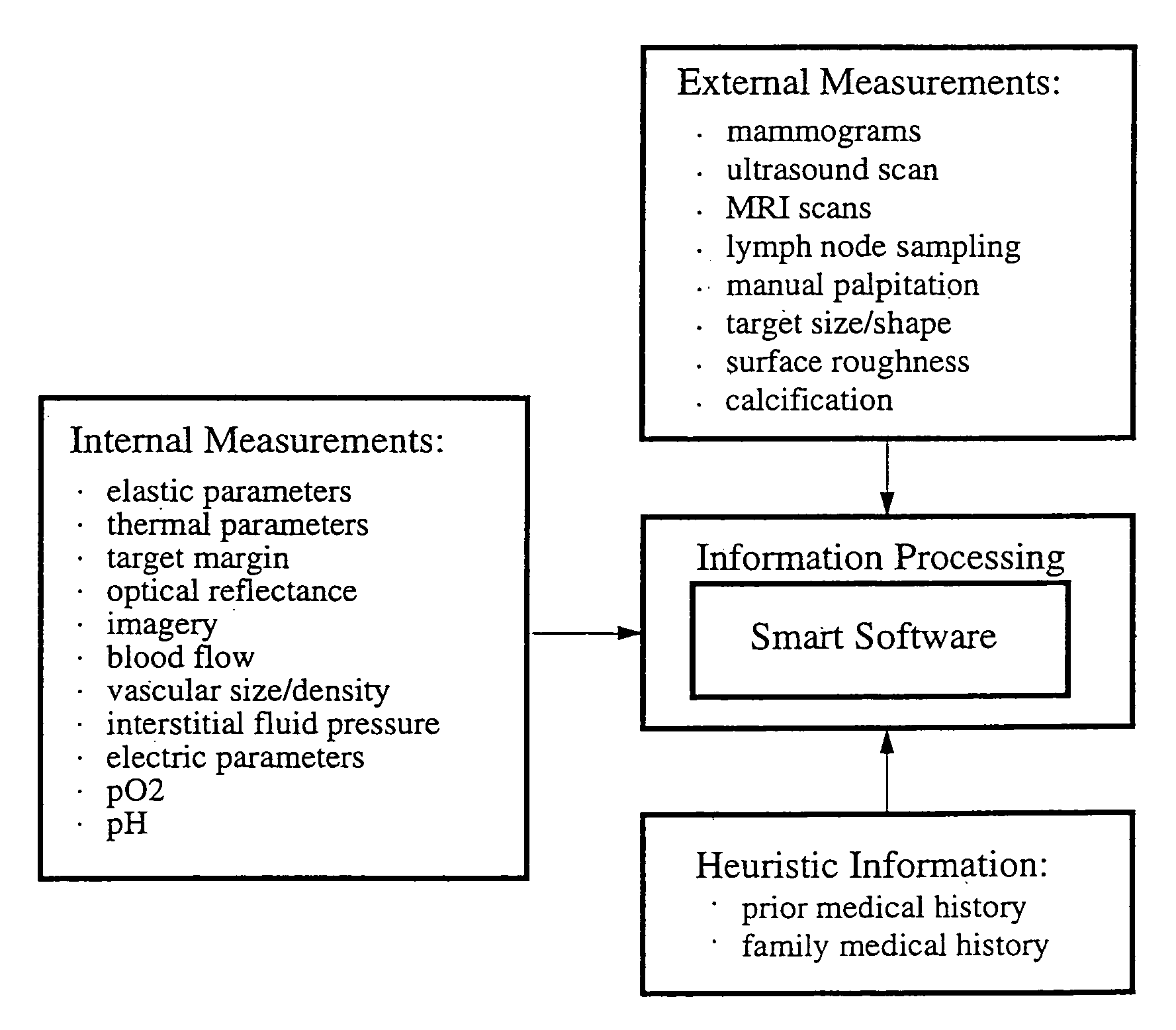
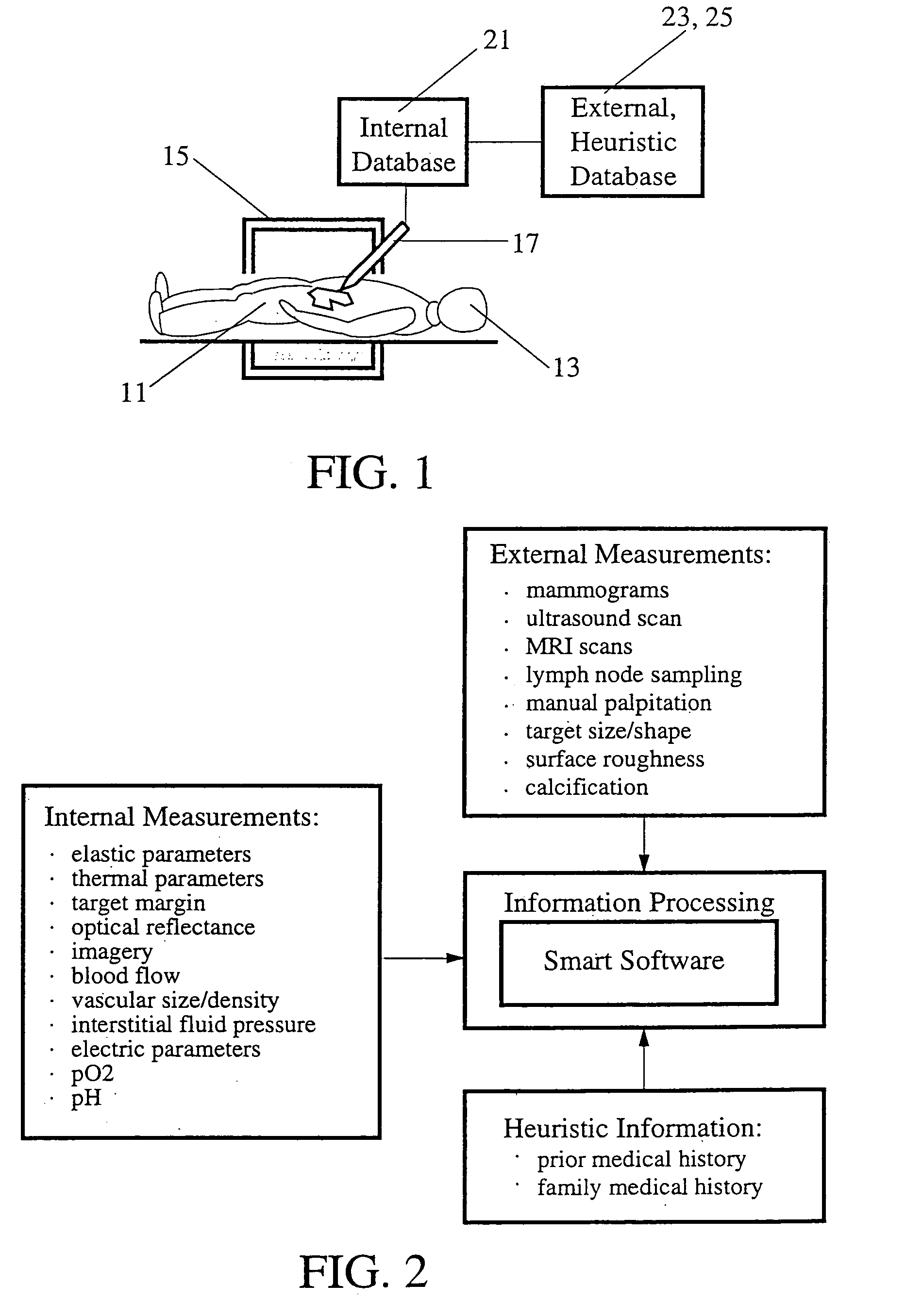
[0017]FIG. 1 illustrates use of the invention to interrogate a target site 11 (organelle, cell, tissue, organ, etc.) in an animal body 13 according to one embodiment of the invention. A sensor or probe is inserted into the body 13 adjacent to the target site 11 and is activated to provide one or more internal measurements, which set forth in more detail in FIG. 2. A region of the body 13 adjacent to the target site is immobilized (to the extent this is possible) by a stereotactic or other body-holding device 15, and a sensor assembly or probe 17 is positioned adjacent to or within the target site, outside or inside the body. Internal measurements data are sensed or measured by the probe 17 and are received and stored by an internal data base 21. An internal data base 22, an external data base 23 and a heuristic database 25 hold internal measurements data external measurements data and heuristic information, respectively, also set forth in greater detail in FIG. 2.

[0018]FIG. 2 sets f...


PUM


Abstract

System and method for performing one or more relevant measurements at a target site in an animal body, using a probe. One or more of a group of selected internal measurements is performed at the target site, is optionally combined with one or more selected external measurements, and is optionally combined with one or more selected heuristic information items, in order to reduce to a relatively small number the probable medical conditions associated with the target site. One or more of the internal measurements is optionally used to navigate the probe to the target site. Neural net information processing is performed to provide a reduced set of probable medical conditions associated with the target site.

Description

[0001]This application is a Division of an application, U.S. Ser. No. 09 / 652,302, filed 28 Aug. 2000, now abdn.ORIGIN OF THE INVENTION[0002]The invention disclosed herein was made by employees of the United States Government and may be manufactured and used by or for the Government for governmental purposes without payment of any royalties for such manufacture and use.FIELD OF THE INVENTION[0003]This invention relates to navigation to, and imaging, sensing, diagnosing, and providing a prognosis for a medical condition of, a target site within a human or animal body.BACKGROUND OF THE INVENTION[0004]Use of a conventional surgical procedure to provide a diagnosis and / or prognosis on a patient is necessarily invasive. Where a surgical probe is used to reduce the invasiveness, the procedure is often performed blindly or with indirect image guidance, with little accurate information on the location of the probe and / or whether the probe has located, navigated to or reached the target site....

Claims


Application Information

Patent Timeline
Patent Type & Authority Patents(United States)
IPC IPC(8): A61B1/00A61B5/00A61B5/026A61B5/03A61B5/0476A61B8/08A61B17/00A61B19/00G06F19/00
CPCA61B5/00A61B5/14539A61B5/415A61B5/418G06F19/345A61B5/0073A61B5/0084A61B5/0261A61B5/031A61B5/0476A61B5/1473A61B8/08A61B19/20A61B19/50A61B2017/00022A61B5/7275A61B90/10A61B34/10G16H50/20A61B5/369
Inventor MAH, ROBERT W.
Owner NASA
Why Eureka
Try Eureka