Energy-saving housing

a technology of energy-saving housing and housing components, applied in the field of energy-saving housing components, can solve the problems of imposing a requiring heating and cooling each room, and conventional energy-saving housing components, etc., and achieves the effects of reducing the load on cooling and heating devices, reducing the burden on the human body, and reducing the burden on the body

Inactive Publication Date: 2005-12-20
HOUSE PORT 23 CO LTD +1
View PDF53 Cites 21 Cited by
  • Summary
  • Abstract
  • Description
  • Claims
  • Application Information

AI Technical Summary

Benefits of technology

[0009]The present invention solves the abovementioned problems of the prior art, and the object thereof is to provide energy-saving housing, wherein comfortable temperatures and humidity conditions can be maintained throughout year with little energ

Problems solved by technology

Therefore, such housing requires costs for heating and cooling each room, and imposes a burden on human bodies due to increased differences in temperature between rooms with air-conditioning and rooms without air-conditioning.
However, conventional energy-saving housing has the following problems.
In Arts A and B, since glass wool is used for heat insulators for walls or the like, the gap between the inner wall and outer wall cannot be completely filled with the heat insulator made from glass wool, so that a gap remains, and since there is a phenomenon in that the heat insulator made from glass wool sags, the gap increases with

Method used


Image

  • Energy-saving housing
  • Energy-saving housing
  • Energy-saving housing

Examples


embodiment

(Embodiment)

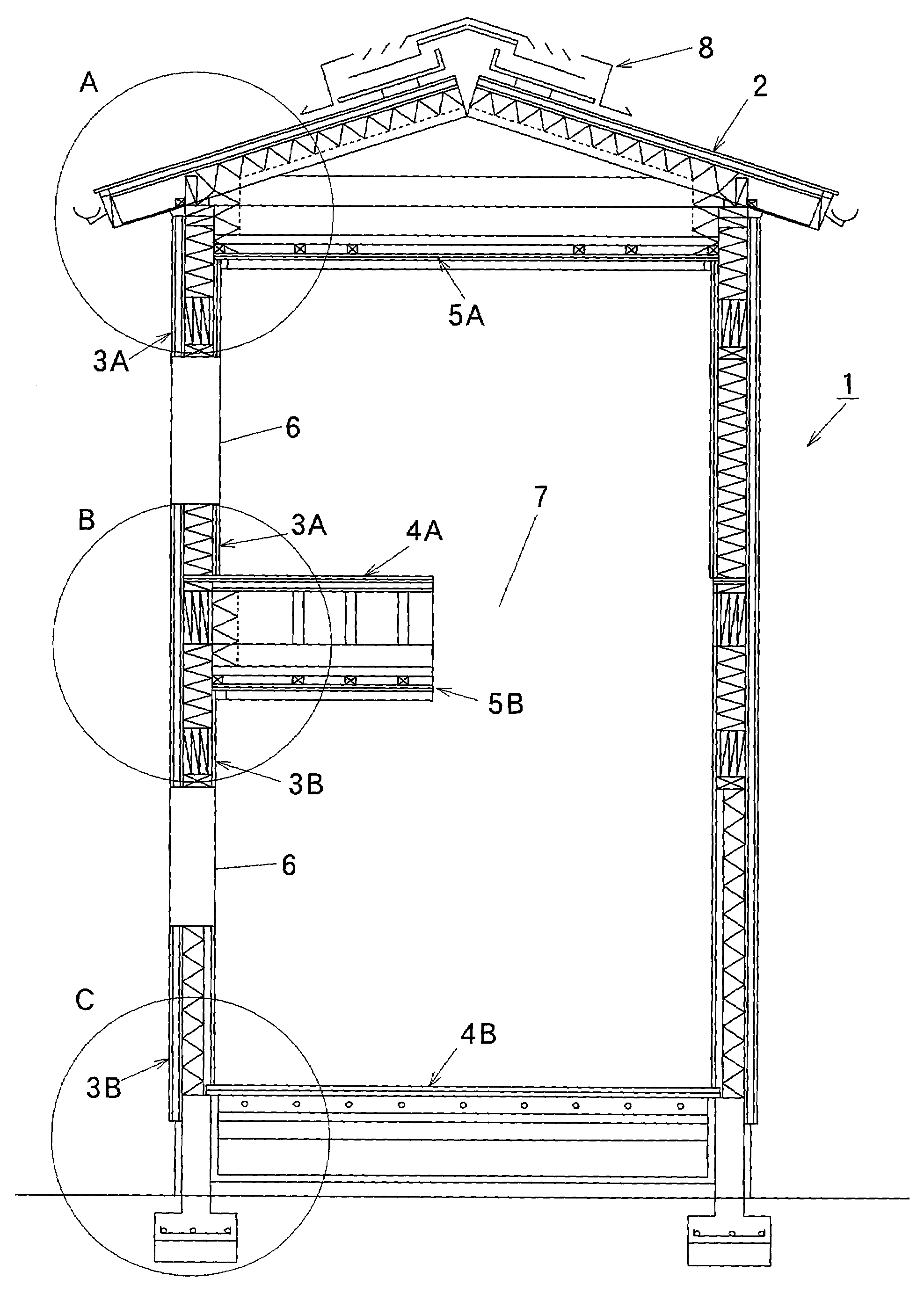
[0069]The energy-saving housing of the invention is explained hereinafter by using an example of two-storied energy-saving housing having a wellhole part with reference to the drawings.

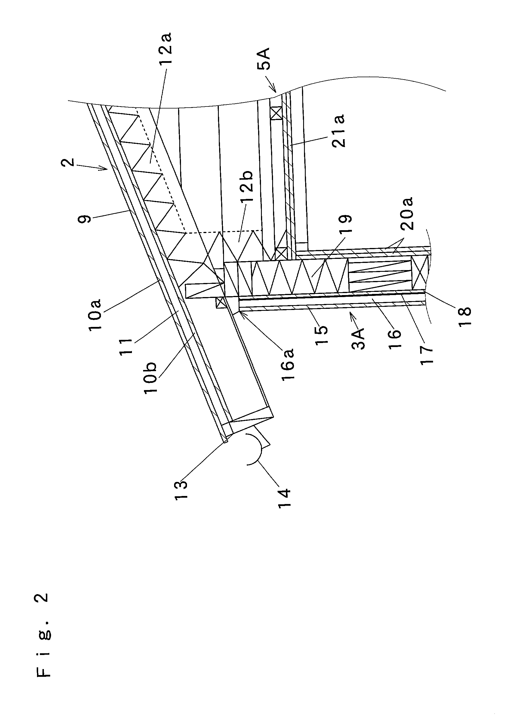
[0070]FIG. 1 is a principal partially sectional view of the two-storied energy-saving housing of the embodiment, FIG. 2 is an enlarged view of the section A of FIG. 1, FIG. 3 is an enlarged view of the section B of FIG. 1, and FIG. 4 is an enlarged view of the section C of FIG. 1.

[0071]In FIG. 1, the numerical reference 1 denotes the two-storied energy-saving housing of this embodiment of the invention. Reference number 2 denotes the roof part of the energy-saving housing 1. Reference number 3A denotes the wall part of the second floor of the energy-saving housing 1. Reference number 3B denotes the wall part of the first floor of the energy-saving housing 1. Reference number 4A denotes the floor part of the second floor of the energy-saving housing 1. Reference number 4B denotes the floor ...


PUM


Abstract

The invention provides energy-saving housing wherein the indoor temperature condition can be made comfortable throughout the year by a small amount of energy by suppressing loads on cooling and heating devices, and high airtightness and high heat insulation performance can be maintained for a long period of time so that durability is excellent. The energy-saving housing includes wall parts provided with inner walling made from an inorganic material and heat insulators made from an organic foamed material, a ceiling part provided with inner walling made from an inorganic material, heat insulators made from an organic foamed material at the ceiling part or roof part, and a floor heating device provided at least at the floor part of the lower floor, and has an equivalent clearance area of from 0.3 cm2/m2 to 0.6 cm2/m2.

Description

BACKGROUND OF THE INVENTION[0001]1. Field of the Invention[0002]The present invention relates to energy-saving housing including residential housing or various facilities including gymnasiums, hospitals, convenience stores, and the like, which are high in airtightness and heat insulation, and can suppress loads on air conditioners, realize comfortable indoor temperatures and humidity conditions, and realize healthy living and working spaces.[0003]2. Description of the Related Art[0004]In conventional housing, air conditioning is carried out for each room by heating systems and cooling systems installed in each room. Therefore, such housing requires costs for heating and cooling each room, and imposes a burden on human bodies due to increased differences in temperature between rooms with air-conditioning and rooms without air-conditioning.[0005]Therefore, recently, housing with a floor heating device for heating the whole housing to reduce the differences in temperature between rooms...

Claims


Application Information

Patent Timeline
IPC IPC(8): E04B1/74E04B1/70E04B1/76E04D13/17F24D3/12F24F7/02
CPCE04B1/74E04D13/174F24F7/02F24D3/14E04B2001/7679Y02B30/00
Inventor HIRAKI, KOJI
Owner HOUSE PORT 23 CO LTD
Why Eureka
Try Eureka