Method and apparatus for humidification and warming of air

a technology of humidification and air, applied in the direction of respirators, machines/engines, combustion-air/fuel-air treatment, etc., can solve the problems of reducing the flow rate of gas even further, requiring a high degree of pressure, and most prior-art devices cannot meet or exceed these ideal characteristics

Inactive Publication Date: 2005-12-20
NORTHGATE TECH
View PDF127 Cites 33 Cited by
  • Summary
  • Abstract
  • Description
  • Claims
  • Application Information

AI Technical Summary

Benefits of technology

[0014]Each of the above aspects provides the advantage of supplying a patient with w

Problems solved by technology

Most prior art devices cannot meet or exceed these ideal characteristics.
Most of these devices generally operate by forcing the gas through t

Method used


Image

  • Method and apparatus for humidification and warming of air
  • Method and apparatus for humidification and warming of air
  • Method and apparatus for humidification and warming of air

Examples


Embodiment Construction

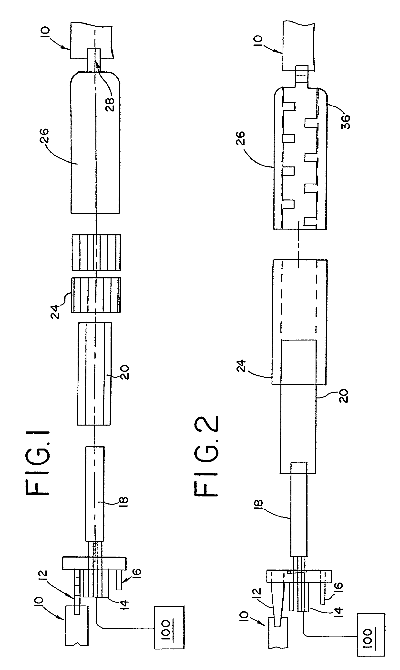
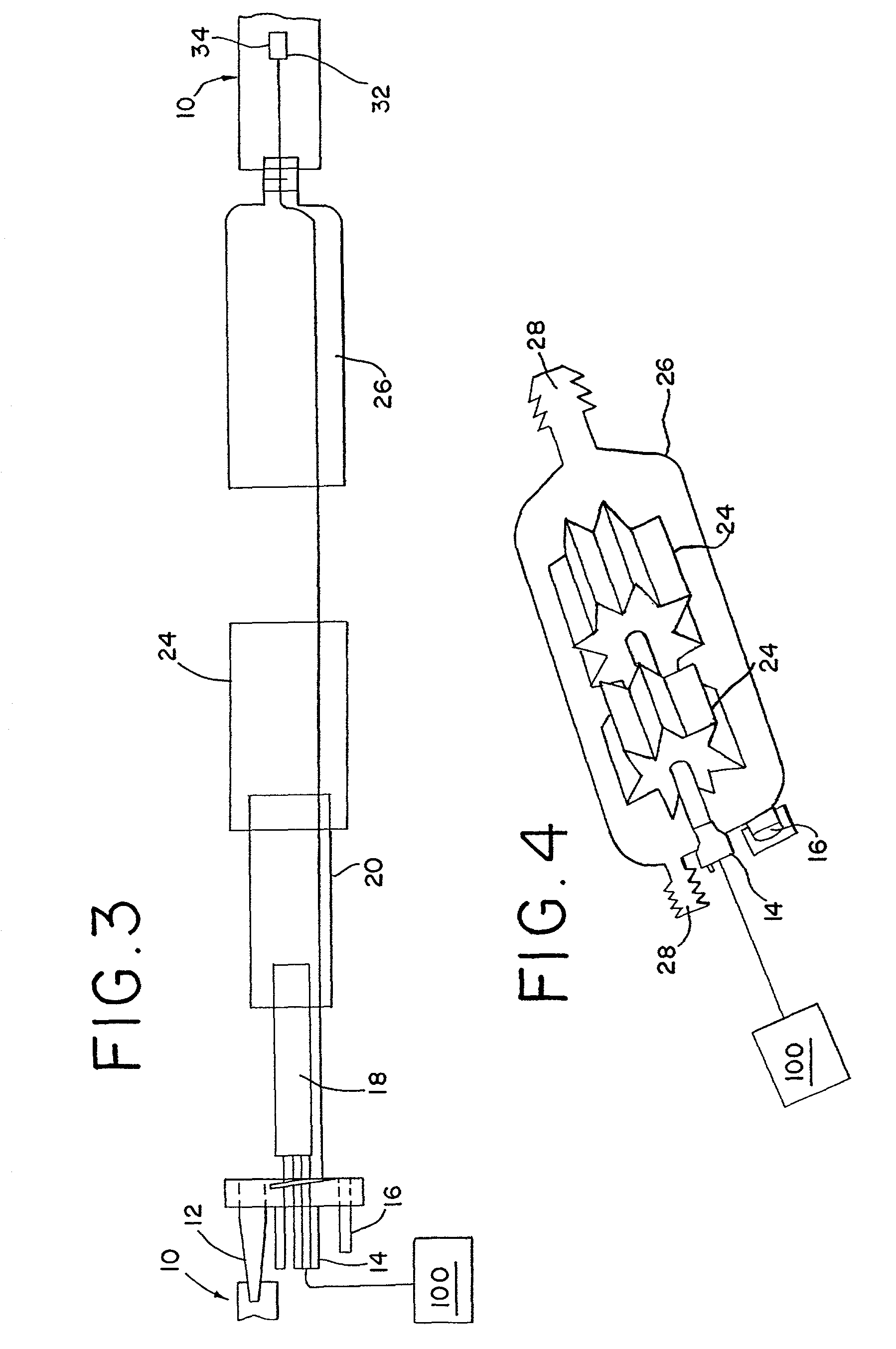
[0034]FIG. 1 shows one embodiment of the gas warmer and humidification apparatus . FIG. 1 shows the apparatus used in conjunction with an insufflation device. FIGS. 1–3 show the apparatus 1 associated with the insufflation tubing 10. In a preferred embodiment, the apparatus is located downstream from the gas source for the insufflation device where downstream refers to a location closer to output of the insufflation tubing 10 or a patient. The apparatus 1 has an upstream end located nearer to the gas source and a downstream end located closer to the patient. The gas warmer and humidifier apparatus 1 may be constructed as a re-useable or disposable product.

[0035]As shown in FIG. 1, in one embodiment, a gas inlet port 12 is located at an upstream end of the apparatus 1 and associable with the insufflation tubing 10. A plurality of plugs 14 may also be located at the upstream end of the apparatus 1. The plugs 14 may be male leads for association with the heater 18 and / or a thermocouple...


PUM


Abstract

A method of humidifying a gas that includes supplying a gas to a surface of a humidification material that readily absorbs moisture and readily releases moisture when exposed to a dry environment and generating turbulence in the gas as it passes over the surface of the humidification material.

Description

[0001]Applicants claim, under 35 U.S.C. § 119(e), the benefit of priority of the filing date of Jun. 30, 2000 of U.S. Provisional Patent Application Ser. No. 60 / 215,442, filed on the aforementioned date, the entire contents of which are incorporated herein by reference.BACKGROUND OF THE INVENTION[0002]1. Field of the Invention[0003]The present invention relates to an apparatus and method used to humidify and / or warm a gas prior to its use in a surgical or other medical procedure.[0004]2. Discussion of Related Art[0005]Many medical and surgical procedures require the supply to a patient of warmed and / or humidified gas at constant high flow rates. Ideally, the flow rate should be approximately 20 liters per minute, the relative humidity should be approximately 80 to 100 percent, and the temperature approximately 90 to 105 degrees Fahrenheit. Most prior art devices cannot meet or exceed these ideal characteristics. The flow rate of many prior devices is well below 20 liters per minute....

Claims


Application Information

Patent Timeline
IPC IPC(8): A61M13/00A61M16/10A61M16/16
CPCA61M13/003Y10S261/65A61M2206/14A61M2205/3368A61M16/16A61M2205/362
Inventor MANTELL, ROBERT R.MANZIE, PETER A.
Owner NORTHGATE TECH
Why Eureka
Try Eureka