Compact ground clamp

Active Publication Date: 2005-12-20
SIGMA ELECTRIC MFG
View PDF10 Cites 66 Cited by
  • Summary
  • Abstract
  • Description
  • Claims
  • Application Information

AI Technical Summary

Benefits of technology

[0004]The present invention provides a compact ground clamp for interconnecting a ground wire to a grounding member wherein upper and lower clamp members are attached by clamping screws for engaging the grounding member and wherein a ground wire boss projects forwardly from the lower clamp member and includes a downwardly opening slot that receives the grounding wire, which is clamped thereto by a set screw

Problems solved by technology

As it is desirable to use a continuous length of grounding wire, the grounding wire needed to be successively threaded through the block hole, a time consuming installation step.

Method used


Image

  • Compact ground clamp
  • Compact ground clamp
  • Compact ground clamp

Examples


Embodiment Construction

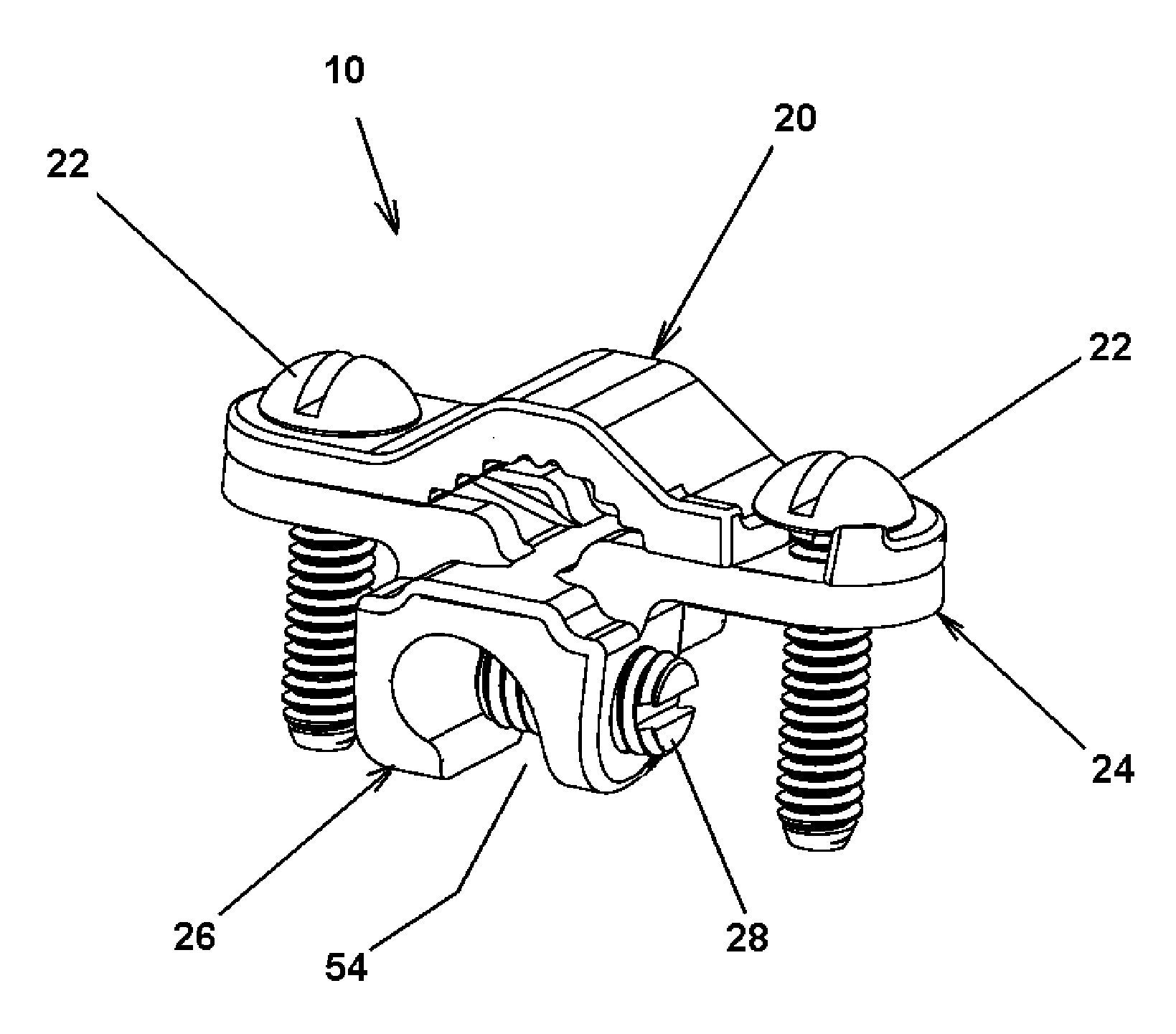
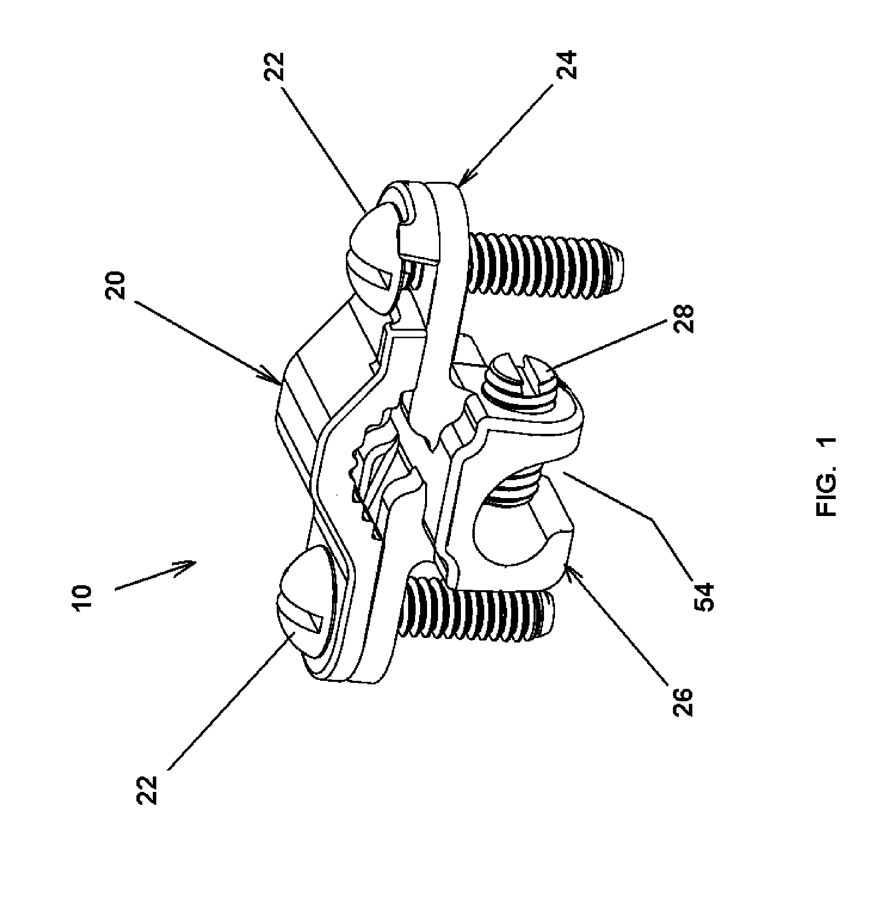
[0016]Referring to the FIGS. 1 and 6, there is shown a ground clamp 10 for establishing a grounding relationship between a ground wire 12 connected with electrical devices to be grounded, and a buried parallel grounding member 14, such as rebar, pipe or ground rod.

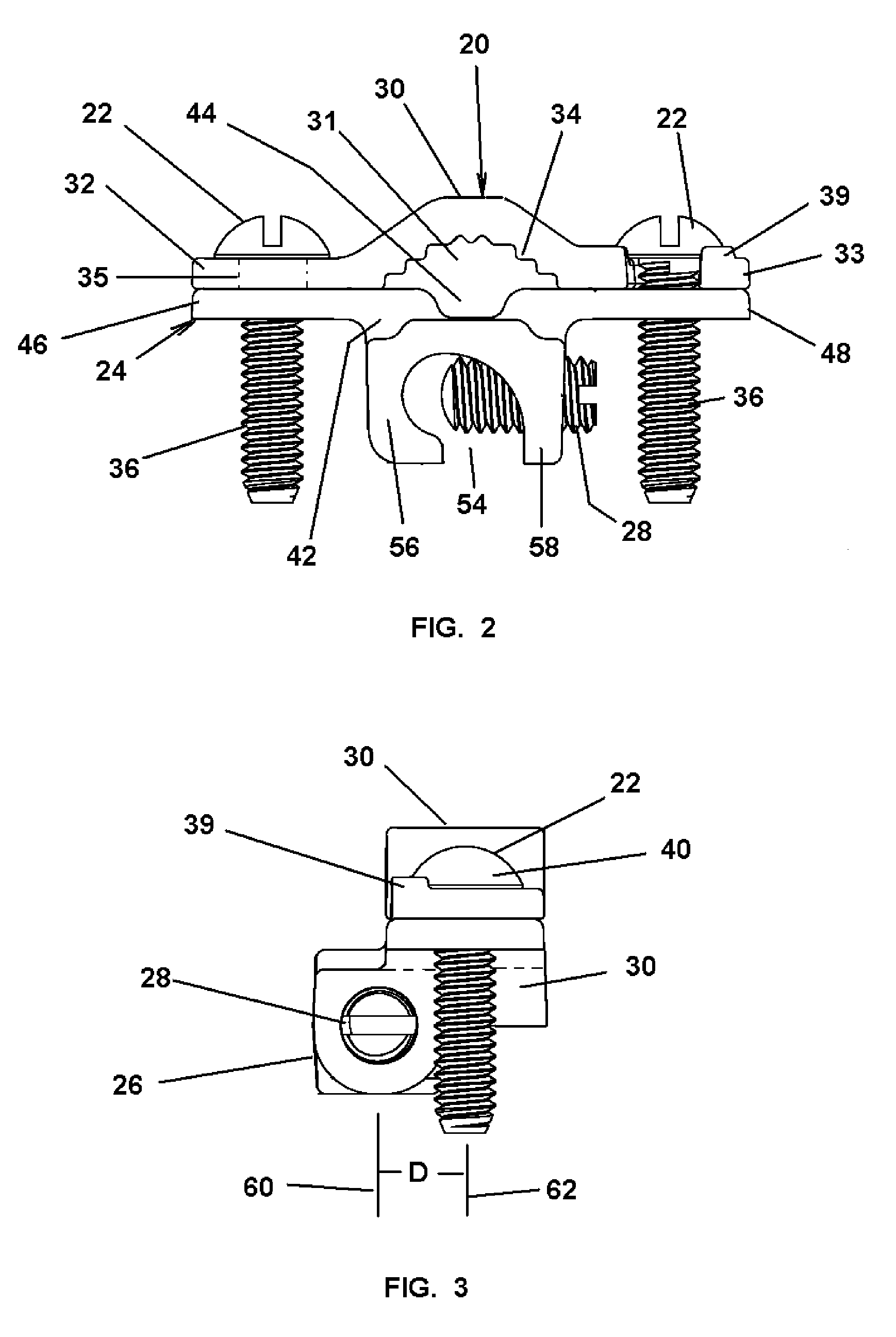
[0017]The ground clamp 10 comprises an upper clamp member 20 connected by threaded clamping screws 22 to a lower clamp member 24 for clamping the grounding member 14 therebetween. The lower clamp member 24 includes a slotted ground wire boss 26 carrying the ground wire 12, which is releasably clamped therein by set screw 28. The clamp members are conventionally formed of suitable conductive material such as copper alloys. The ground clamp is configured to handle a customary range of ground wire and grounding member sizes. The range for the ground wire would typically be #10 through #2. The clamp would typically accommodate rigid conduit, copper tubing, and rebar from ⅜ inch to ¾ inch diameter.

[0018]Referring to FIGS. 2 thr...


PUM


Abstract

A ground clamp having upper and lower clamp members interconnected by clamping screws for mechanical and electrical connection with a grounding member, and a frontally projecting boss on the lower clamp member having a downwardly opening slot for receiving a ground wire which is retained by a set screw forward of the clamping screws whereby the various screws may be independently tightened without interference from adjacent screws.

Description

FIELD OF THE INVENTION[0001]The present invention relates to electrical connectors for ground wires and, in particular, a ground clamp for connecting a grounding wire to a parallel grounding member.BACKGROUND OF THE INVENTION[0002]Grounding connectors are used to electrically connect electrical devices to a grounding members, such as ground rods, pipe and rebar. Inasmuch as the connectors are typically installed underground or in limited access space, the compactness and ease of use are primary concerns. One prior art device for connecting a grounding wire to a parallel grounding member includes a pair of clamp members that are interconnected by clamping screws for clamping the ground member therebetween. A block is provided on the top clamp member having a transverse through hole for receiving the grounding wire. A vertical set screw is provided for clamping the grounding wire in the block. The upper vertical location of the block increases the overall envelope size of the ground c...

Claims


Application Information

Patent Timeline
IPC IPC(8): H01R4/36H01R4/46H01R9/24H01R12/00
CPCH01R4/46H01R9/2483H01R4/36
Inventor SHUKLA, SHUKLESHIYER, KRISHNAN S.KHARAS, NEVILLE N.
Owner SIGMA ELECTRIC MFG
Why Eureka
Try Eureka