Fully differential input buffer with wide signal swing range

a fully differential input and buffer technology, applied in the field of differential input buffers, can solve the problems of reducing sndr, affecting the signal swing range of the unit-gain input buffer, and affecting the output signal, so as to increase the gate voltage of the bias transistor, prevent output distortion, and improve the effect of linearity

Inactive Publication Date: 2005-12-20
AVAGO TECH WIRELESS IP SINGAPORE PTE
View PDF2 Cites 10 Cited by
  • Summary
  • Abstract
  • Description
  • Claims
  • Application Information

AI Technical Summary

Benefits of technology

[0008]A squeezable tail current source for use in a differential operational amplifier is disclosed that regulates the current through a main input differential pair while preventing output distortion and allowing high linearity. According to an embodiment of the present invention, the squeezable tail current source includes a first transistor pair that replicates a main input transistor pair, wherein both the first transistor pair and the main input transistor pair receive a common voltage input at their respective gates. The squeezable tail current source also includes a second transistor pair, a bias transistor, a first current source, a folding transistor, and a second current source that biases the folding transistor. These components are configured such that current through the main input transistor pair is maintained as the voltage input varies. Current through the second transistor pair and the bias transistor is squeezed as the voltage input is decreased, thereby increasing a gate voltage of the bias transistor, and thereby causing current through both the first transistor pair and the main input transistor pair to remain nearly constant. In addition, the second current source and the folding transistor isolate the bias transistor and the second transistor pair from a drain voltage of the first transistor pair, thereby causing the first transistor pair and the main input transistor pair to have a common drain bias, which prevents output distortion and allows high linearity to be achieved.
[0011]In this differential input buffer embodiment, the first main input transistor pair, the first replica transistor pair, the first tail transistor pair, the first bias transistor, and the first current source are configured such that current through the first main input transistor pair is maintained as the first common voltage input to the first main input pair varies. Similarly, the second main input transistor pair, the second replica transistor pair, the second tail transistor pair, the second bias transistor, and the second current source are configured such that current through the second main input transistor pair is maintained as the voltage input to the second main input pair varies. In embodiments of the present invention, current through a tail transistor pair and its corresponding bias transistor is squeezed as the voltage input to the corresponding main input pair is decreased. This increases a gate voltage of the bias transistor and causes current through both the corresponding replica transistor pair and main transistor pair to remain nearly constant.
[0012]In an embodiment of the present invention, the first biasing current source and the first folding transistor isolate the first bias transistor and the first tail transistor pair from a drain voltage of the first replica transistor pair, thereby causing the first replica transistor pair and the first main input transistor pair to have a common drain bias. Similarly, the second biasing current source and the second folding transistor isolate the second bias transistor and the second tail transistor pair from a drain voltage of the second replica transistor pair, thereby causing the second replica transistor pair and the second main input transistor pair to have a common drain bias. When the replica transistor pair and corresponding main input transistor pair have a common drain bias, output distortion is prevented and high linearity is achieved.

Problems solved by technology

When a supply voltage is reduced, the signal swing that the unit-gain input buffer can handle is limited due to reduced headroom.
This limitation causes a reduction in SNDR.
Linearity is important because harmonic distortion results in spillover from data bin to data bin that may corrupt the data spectrum.

Method used


Image

  • Fully differential input buffer with wide signal swing range
  • Fully differential input buffer with wide signal swing range
  • Fully differential input buffer with wide signal swing range

Examples


Embodiment Construction

[0024]While the present invention is described herein with reference to illustrative embodiments for particular applications, it should be understood that the invention is not limited thereto. Those skilled in the art with access to the teachings provided herein will recognize additional modifications, applications, and embodiments within the scope thereof and additional fields in which the present invention would be of significant utility.

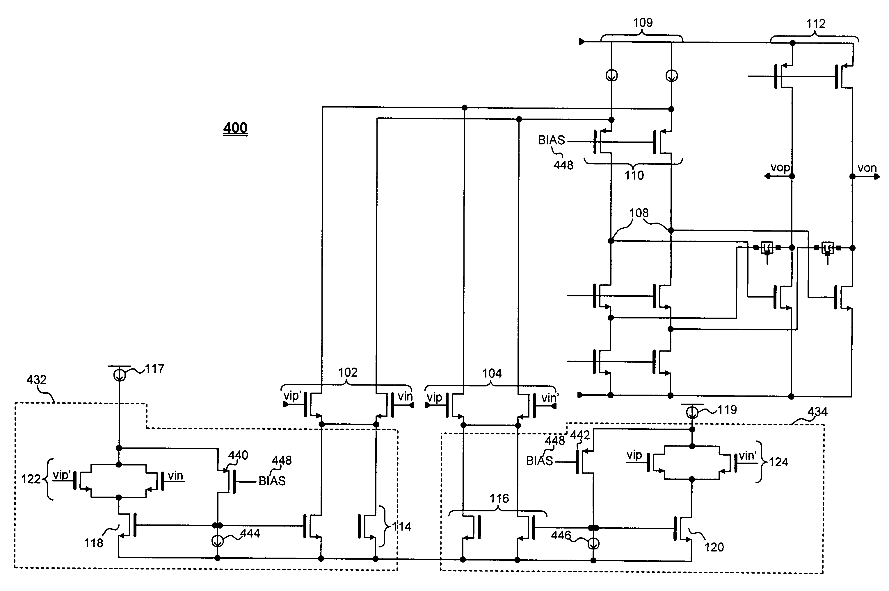
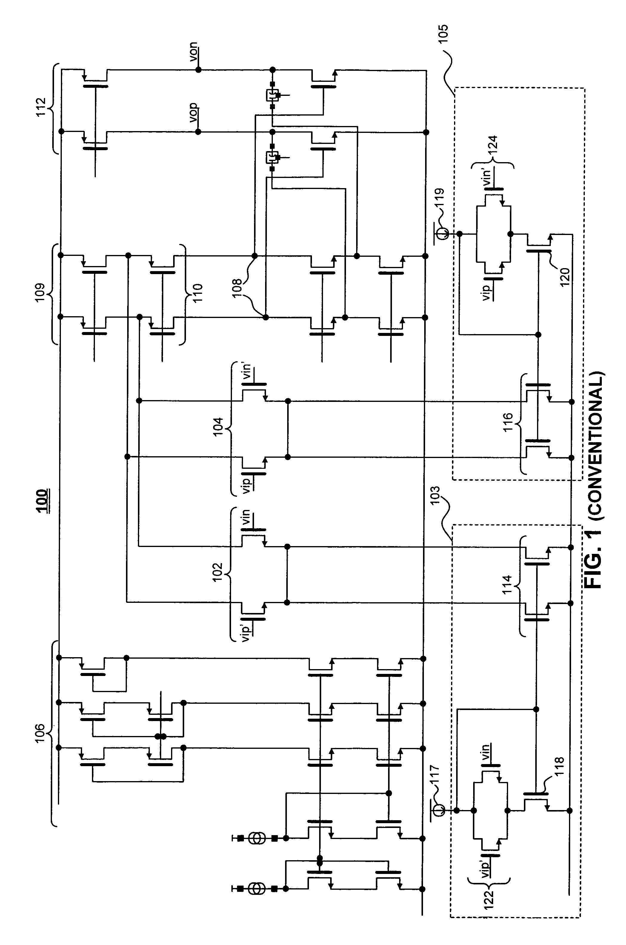
[0025]FIG. 1 illustrates a conventional four-input differential operational amplifier with squeezable tail current. Differential operational amplifier 100 has four input terminals represented by transistors forming main input differential pairs 102 and 104. Differential pair 102 has inputs vip′ and vin. Differential pair 104 has inpus vip and vin′. The transistor banks 106 are bias transistors. An output 108 of a first stage 109 of the amplifier is located at the drains of transistor pair 110, which feed into an input of a second stage 112 of the ...


PUM


Abstract

A squeezable tail current source for use in a differential operational amplifier is disclosed that regulates the current through a main input differential pair while preventing output distortion and allowing high linearity. The squeezable tail current source includes a first transistor pair that replicates a main input transistor pair, wherein both the first transistor pair and the main input transistor pair receive a common voltage input at their respective gates. The squeezable tail current source also includes a second transistor pair, a bias transistor, a first current source, a folding transistor, and a second current source that biases the folding transistor. These components are configured such that current through the main input transistor pair is maintained as the voltage input varies. In addition, the second current source and the folding transistor isolate the bias transistor and the second transistor pair from a drain voltage of the first transistor pair, thereby causing the first transistor pair and the main input transistor pair to have a common drain bias, which prevents output distortion and allows high linearity to be achieved.

Description

BACKGROUND OF THE INVENTION[0001]1. Field of the Invention[0002]This invention relates generally to processors with an analog-to-digital conversion interface and a buffer to drive the input. More particularly, this invention relates to differential input buffers, such as used in programmable gain amplifiers of Asymmetric Digital Subscriber Line (ADSL) receivers.[0003]2. Related Art[0004]The Asymmetric Digital Subscriber Line (ADSL) is one of the new technologies used for high-speed Internet access. Data rates up to 9 Mb / s are currently available in the standard ADSL offering. An ADSL transmission system is specified in a frequency-division multiplexed scheme, with the downstream (i.e., central office to customer) utilizing a frequency range of approximately 160 kHz to 1.104 MHz and upstream (i.e., customer to central office) utilizing a frequency range of approximately 30 kHz to 138 kHz. In each frequency domain, the frequencies are divided into data bins with 4 kHz frequency spacin...

Claims


Application Information

Patent Timeline
Patent Type & Authority Patents(United States)
IPC IPC(8): H03F3/45H03K19/0175H03K19/094
CPCH03F3/45192H03F3/45708H03F2203/45361H03F2203/45401H03F2203/45406
Inventor LI, HUNG-SUNG
Owner AVAGO TECH WIRELESS IP SINGAPORE PTE
Why Eureka
Try Eureka