Stereoscopic picture separation for phosphor lag reduction in PDP

a technology of phosphor lag reduction and stereoscopic picture separation, which is applied in the field of stereoscopic display methods and devices, can solve the problems of reducing a lot of image brightness, time parallax between the two, and the possibility of ghosting between, and achieves the effect of less luminan

Inactive Publication Date: 2005-12-20
THOMSON LICENSING SA
View PDF9 Cites 37 Cited by
  • Summary
  • Abstract
  • Description
  • Claims
  • Application Information

AI Technical Summary

Benefits of technology

[0020]The method according to the invention is based on a specific reorganization of sub-fields. From a further European Patent Application of the applicant having the application number 01103185.3 it is known a concept in which for corresponding pixels of the original left picture and the original right picture sub-field code words are determined that have identical entries for a number of sub-fields called common sub-fields. This idea is based on the observation that in stereoscopic vision most of the corresponding picture elements in the left and right picture have great similarities. Apart from the common sub-fields there are specific right and specific left sub-fields for the right and left pictures. The common sub-fields can be grouped together and then they are positioned in the frame period between the group of specific left sub-fields and the group of specific right sub-fields. The opening periods of the shutters for the left and right eye overlap during the period where the common sub-fields are positioned. This allows for the production of more light pulses in the left and right picture and the stereoscopic pictures are much brighter. In another embodiment of this application the sub-fields of the groups can be arranged in interleaved fashion for reducing the time parallax problem.
[0021]For the effective phosphor lag effect reduction it is now the general idea of a first embodiment of the invention to duplicate the group of common sub-fields preferably with reduced sub-field weights and to position a common sub-field group behind the specific right sub-field group and behind the specific left sub-field group. With this sub-field arrangement it is assured that the ghost image from the left picture seen by the right eye is originating from the group of common sub-fields the light of which is dedicated to both eyes anyhow. The same holds for the ghost image of the right picture conversely. Advantageously the Phosphor Lag effect is reduced in case of stereoscopic displaying and no flicker is introduced.

Problems solved by technology

Nevertheless, this method can introduce other discomfort such as the introduction of time parallax between the two images, or the possibility of “ghosting” between the image due to phosphor persistence.
The electro-optical polarizing shutters available on the market today transmit only 30% of the unpolarized input light (rather than 50% for perfect polarizers) and this reduces a lot the image brightness.
The display of stereo pictures on a Plasma screen is not a simple matter of design choice, because it needs to display two different pictures per frame period which is a new challenge for this technology if one does not want to accept a great reduction of frame repetition frequency.

Method used


Image

  • Stereoscopic picture separation for phosphor lag reduction in PDP
  • Stereoscopic picture separation for phosphor lag reduction in PDP
  • Stereoscopic picture separation for phosphor lag reduction in PDP

Examples


Embodiment Construction

[0036]Preferred embodiments of the present invention will be explained along with FIGS. 6 to 10.

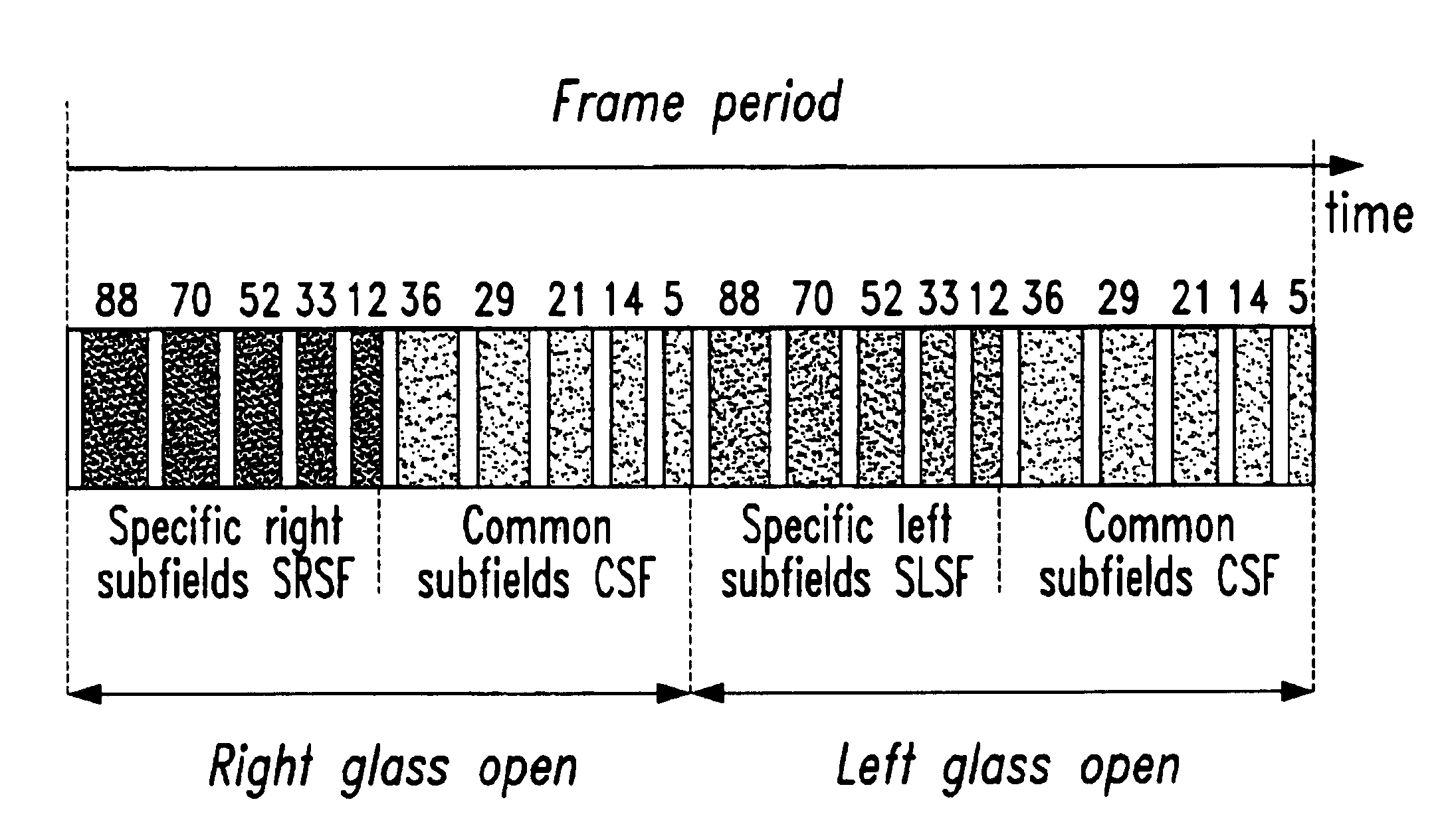
[0037]A first embodiment of the invention is based on a specific-common sub-field encoding with stereoscopic pictures separation as mentioned above. The principle of the specific-common sub-field encoding is described in the previous application EP 01103185.3 of the applicant. For the purpose of the disclosure of this application it is therefore expressively referred also to the former application. The basic idea behind this concept is to apply three images instead of two: instead of the right and left images, three images, namely a specific-right one, a specific-left one and a common one are considered.

[0038]This concept is based on the fact that the two original pictures are two views from the same scene with lots of similarities. A pair of Right(R) and Left(L) images will be converted in three pictures: Specific Right(R′), Specific Left(L′) and (C′) which is the common one. This conver...


PUM


Abstract

For stereoscopic displaying the new plasma display panels are providing promising results. When using shutter glasses that are controlled by the PDP, it is possible to display left and right image in short succession for stereoscopic displaying. However, there is the phosphor lag effect that is really disturbing and can totally impede the stereovision. The frame period of a stereoscopic picture is divided to at least one left period and at least one right period for the left picture and the right picture respectively. According to the invention both pictures are analyzed for similarities and the common part for a pair of corresponding pixels is determined. Sub-field code words for the left / right picture are determined having a part for the specific left / right sub-fields and a part for the common sub-fields. The common sub-fields are positioned at the end of each left / right field for the left / right picture so that the phosphor lag effect is no longer visible.

Description

BACKGROUND OF THE INVENTION[0001]The present invention relates to a method and device for processing video frames for stereoscopic display on a display device, particularly a Plasma Display Panel (PDP), having a plurality of luminous elements. In each case one or more of them belongs to a pixel of a video frame. Wherein each video frame includes a left and a right picture and the time duration of the video frame is divided into a plurality of sub-fields during which the luminous elements can be activated for light emission / generation in small pulses corresponding to a sub-field code word which is used for brightness control.[0002]The 3D perception from the Human Visual System (HVS) is based on the close side-by-side positioning of the eyes. Each eye takes a view of the same area from a slightly different angle. These two separate images are sent to the brain for processing according to FIG. 1. When the two images arrive simultaneously in the back of the brain, they are united into o...

Claims


Application Information

Patent Timeline
Patent Type & Authority Patents(United States)
IPC IPC(8): H04N5/66G09G3/00G09G3/20G09G3/28H04N13/122H04N13/239
CPCG09G3/003G09G3/2029H04N13/0018H04N13/0037H04N13/0048H04N13/0051H04N13/0422H04N13/0438H04N13/0497H04N19/597G09G3/28G09G2320/0247G09G2320/0257H04N13/0029H04N13/0055H04N13/0059H04N13/0239H04N13/0285H04N13/0431H04N13/0456G09G3/288H04N13/341H04N13/167H04N13/194H04N13/189H04N13/324H04N13/122H04N13/161H04N13/334H04N13/286H04N13/15H04N13/239H04N13/139H04N13/361H04N13/398H04N13/00
Inventor WEITBRUCH, SEBASTIENFLOURY, ALEXA
Owner THOMSON LICENSING SA
Why Eureka
Try Eureka