System and method for jitter compensation in data transfers

a data transfer and jitter compensation technology, applied in the field of data communication in computer systems, can solve the problems of not having enough data in the buffer to be retransmitted, affecting the retransmission speed of data, so as to simplify the comparison logic and reduce the number

Inactive Publication Date: 2005-12-20
CF DB EZ +1
View PDF14 Cites 75 Cited by
  • Summary
  • Abstract
  • Description
  • Claims
  • Application Information

AI Technical Summary

Benefits of technology

[0010]In one embodiment, the system comprises a circularly accessed buffer coupled to read and write logic. The read and write logic access data words at locations within the circular buffer as indicated by respective read and write pointers. The system further comprises control logic which compares the pointers to determine whether the buffer is approaching an underflow or overflow condition and adds or deletes fill words between frames of data to compensate for the impending underflow or overflow condition. Fill words are added or deleting by manipulating the read or write pointer to re-read or overwrite fill words when necessary. In one embodiment, the system includes fill word logic which is configured to add a fill word bit to each received word and to set or clear the fill word bit to indicate whether or not the corresponding word is a fill word. In one embodiment, the system compares read and write pointers only when one of the pointers has a value of 0 in order to reduce the number of times they are compared and thus to simplify the comparison logic.

Problems solved by technology

As a result, the jitter could increase enough to corrupt the data.
As a result, the buffer in which the received data is stored until it is retransmitted may exceed its capacity (an overflow condition,) or there may not be sufficient data in the buffer to be retransmitted (an underflow condition.)
This problem can be compounded each time the frames pass through one of the devices in the loop.
Unless there is some means to compensate for this problem, corruption of the data may occur.

Method used


Image

  • System and method for jitter compensation in data transfers
  • System and method for jitter compensation in data transfers
  • System and method for jitter compensation in data transfers

Examples


Embodiment Construction

[0018]A preferred embodiment of the invention is described below. It should be noted that this embodiment and other embodiments described below are exemplary and are intended to be illustrative of the invention rather than limiting.

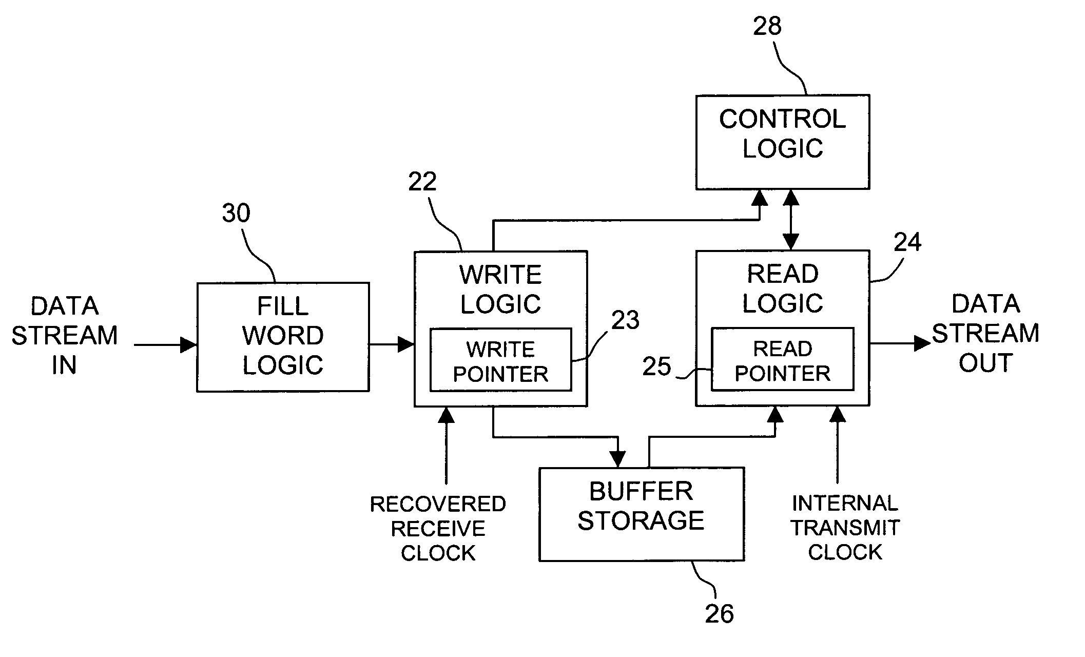
[0019]Broadly speaking, the invention comprises a system and method for using pointers to indicate read and write locations in a clocked circular buffer and comparing the pointers to determine whether fill words between frames should be added or deleted to prevent overflow or underflow of data from the buffer. If the write pointer leads the read pointer by more than a predetermined amount (approaching overflow,) the write pointer pauses and overwrites a fillword (effectively deleting a fillword,) allowing the read pointer to catch up to the write pointer. If the write pointer leads the read pointer by less than a predetermined amount (approaching underflow,) the read pointer pauses, re-reading the same fill word (effectively adding another fill word to th...


PUM


Abstract

A system and method for compensating for differences between a recovered receive clock and an internal transmit clock in an elastic buffer and thereby preventing corruption of data. In one embodiment, the system comprises a circularly accessed buffer coupled to read and write logic. The read and write logic read and write to locations within the circular buffer as indicated by respective read and write pointers. The system further comprises control logic which compares the pointers to determine whether the buffer is approaching an underflow or overflow condition and adds or deletes fill words between frames of data to compensate for the underflow or overflow condition. In one embodiment, the system includes fill word logic which is configured to add a fill word bit to each received word and to set or clear the fill word bit to indicate whether or not the corresponding word is a fill word.

Description

[0001]This application claims the benefit of the filing date of U.S. Provisional Patent Application Ser. No. 60 / 202,720 by inventors Michael A. Nelson and Tom Bucht, entitled “System and Method for Jitter Compensation in Data Transfers” filed on May 8, 2000.FIELD OF THE INVENTION[0002]The invention relates generally to data communication in computer systems, and more particularly to a system and method implemented in connection with serial data packet protocols which re-time received frames to an asynchronous transmit clock wherein overflow or underflow conditions are detected in an elastic buffer and corrected.BACKGROUND OF THE INVENTION[0003]Individual computer systems can be combined to form networks. There are many different types of networks, including local area networks (LANs,) wide area networks (WANs,) storage area networks (SANs) and many others. Networks are typically characterized by several characteristics, including their protocols, their architectures and their topolo...

Claims


Application Information

Patent Timeline
Patent Type & Authority Patents(United States)
IPC IPC(8): G06F5/10G06F5/14
CPCG06F5/14G06F2205/062
Inventor NELSON, MICHAEL A.BUCHT, THOMAS W.
Owner CF DB EZ
Why Eureka
Try Eureka