
Apparatus and method for generating and displaying a schema diagram for a database

a database and schema technology, applied in the field of computer systems, can solve the problems of inefficient tools and methods for administrating databases, increased complexity of databases, time-consuming and inefficient,

Inactive Publication Date: 2005-12-20
IBM CORP
View PDF5 Cites 28 Cited by
  • Summary
  • Abstract
  • Description
  • Claims
  • Application Information

AI Technical Summary

Benefits of technology

The invention is an apparatus and method for creating a diagram of a database. It automatically queries the database to determine its objects and relationships, and generates a visual representation of the database. The system can also filter which objects and relationships are included in the diagram and which ones are displayed. This makes it easier for users to understand the structure of the database.

Problems solved by technology

Many modern computer systems are a complex combination of different hardware and software that are interconnected on a network.
As the need for databases has grown, the complexity of databases has grown as well.
This effort is manual, time-consuming and inefficient.
Without a way for a database administrator to easily generate and graphically view database schema, the computer industry will continue to suffer from inefficient tools and methods of administrating databases.

Method used


Image

  • Apparatus and method for generating and displaying a schema diagram for a database
  • Apparatus and method for generating and displaying a schema diagram for a database
  • Apparatus and method for generating and displaying a schema diagram for a database

Examples


Embodiment Construction

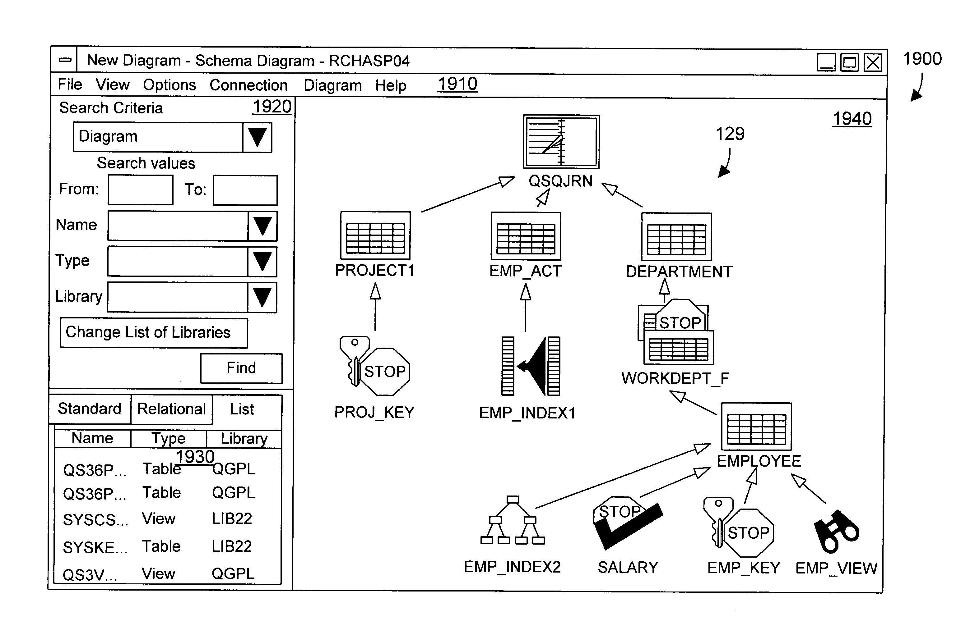
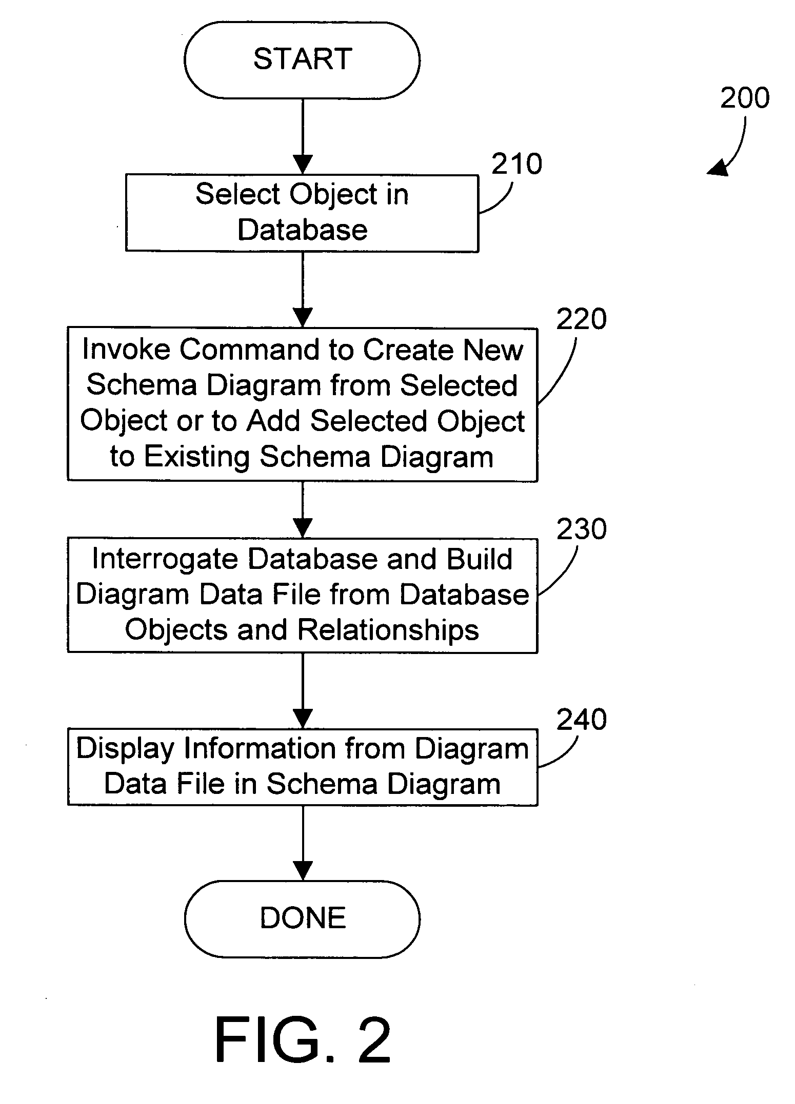
[0017]The present invention relates to generating a visual representation of a database, referred to herein as a schema diagram. According to preferred embodiments of the present invention, a user can select any object in a database and invoke a menu function to automatically generate and display a schema diagram for the database.

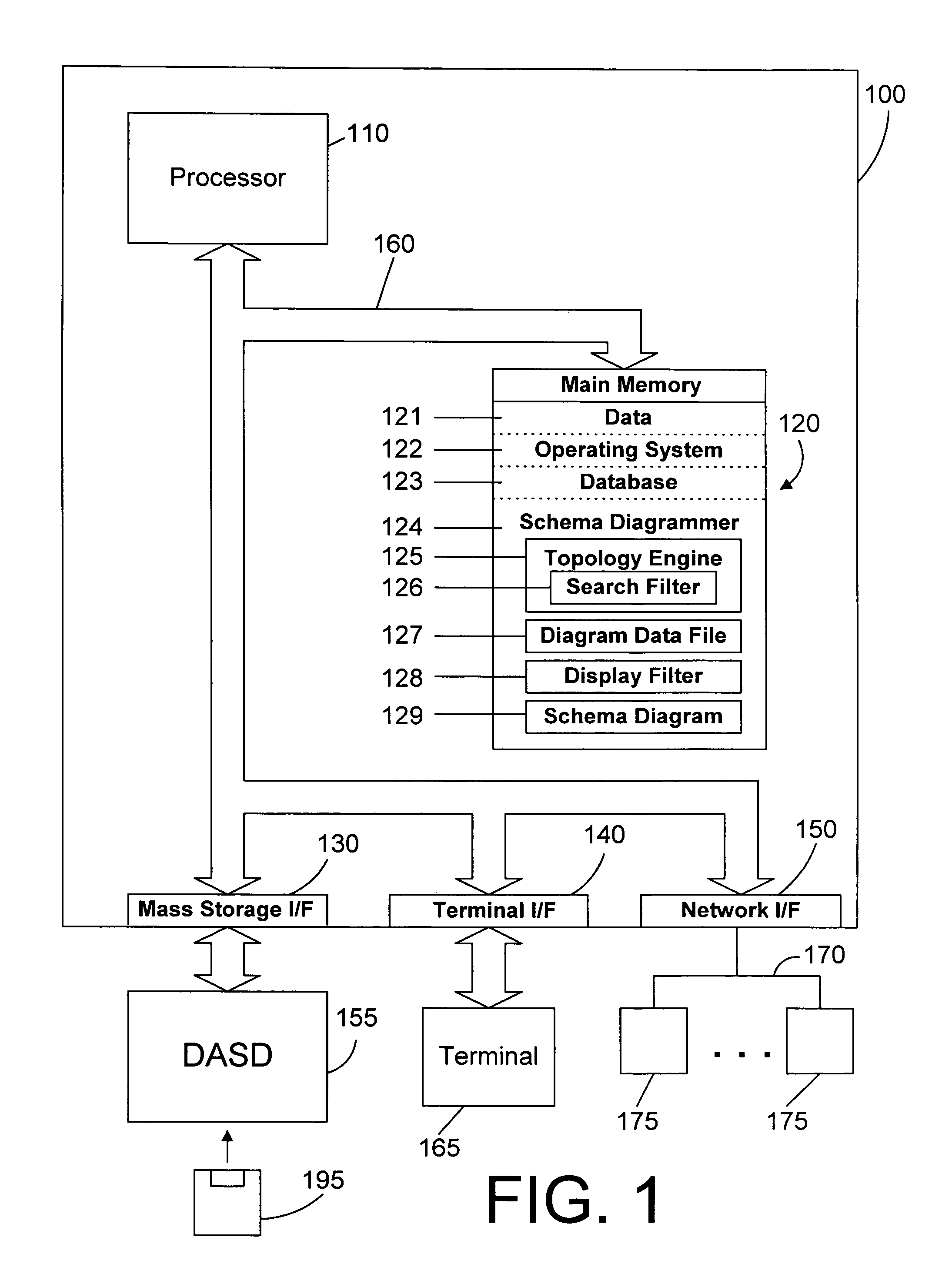
[0018]Referring to FIG. 1, a computer system 100 in accordance with the preferred embodiment is an enhanced IBM AS / 400 computer system. However, those skilled in the art will appreciate that the mechanisms and apparatus of the present invention apply equally to any computer system, regardless of whether the computer system is a complicated multi-user computing apparatus or a single user workstation. As shown in FIG. 1, computer system 100 comprises a processor 110 connected to a main memory 120, a mass storage interface 130, a terminal interface 140, and a network interface 150. These system components are interconnected through the use of a system bus 160....


PUM


Abstract

An apparatus and method for generating and displaying a schema diagram of a database includes a schema diagrammer that automatically queries a database to determine its objects and relationships, and generates a graphical representation of the database in the form of a schema diagram that is displayed to the user. The schema diagrammer may optionally include a search filter to potentially constrain which objects and relationships in the database are included in a diagram data file, and a display filter to potentially constrain which objects and relationships stored in the diagram data file are displayed in the schema diagram.

Description

BACKGROUND OF THE INVENTION[0001]1. Technical Field[0002]This invention generally relates to computer systems and more specifically relates to an apparatus and method for displaying information relating to a database to a user.[0003]2. Background Art[0004]Since the dawn of the computer era, computer systems have evolved into extremely sophisticated devices that may be found in many different settings. Computer systems typically include a combination of hardware (e.g., semiconductors, circuit boards, etc.) and software (e.g., computer programs). As advances in semiconductor processing and computer architecture push the performance of the computer hardware higher, more sophisticated computer software has evolved to take advantage of the higher performance of the hardware, resulting in computer systems today that are much more powerful than just a few years ago.[0005]Many modern computer systems are a complex combination of different hardware and software that are interconnected on a n...

Claims


Application Information

Patent Timeline
Patent Type & Authority Patents(United States)
IPC IPC(8): G06F17/00G06F17/30
CPCG06F17/30604G06F16/288
Inventor JOHNSON, PETER JOHNPFEIFER, MICHAEL DONALD
Owner IBM CORP
Learn More