

Protractor and ruler combination
a protractor and ruler technology, applied in the field of protractor and ruler combination, can solve the problems of user inability to identify the included angle between the ruler b>20, the protractor , inconvenience for the user in identification, and achieve the effect of preventing the ink of the pen from infiltrating the surface and facilitating the user to operate the protractor
- Summary
- Abstract
- Description
- Claims
- Application Information
AI Technical Summary
Benefits of technology
Problems solved by technology
Method used
Image

Examples
Embodiment Construction
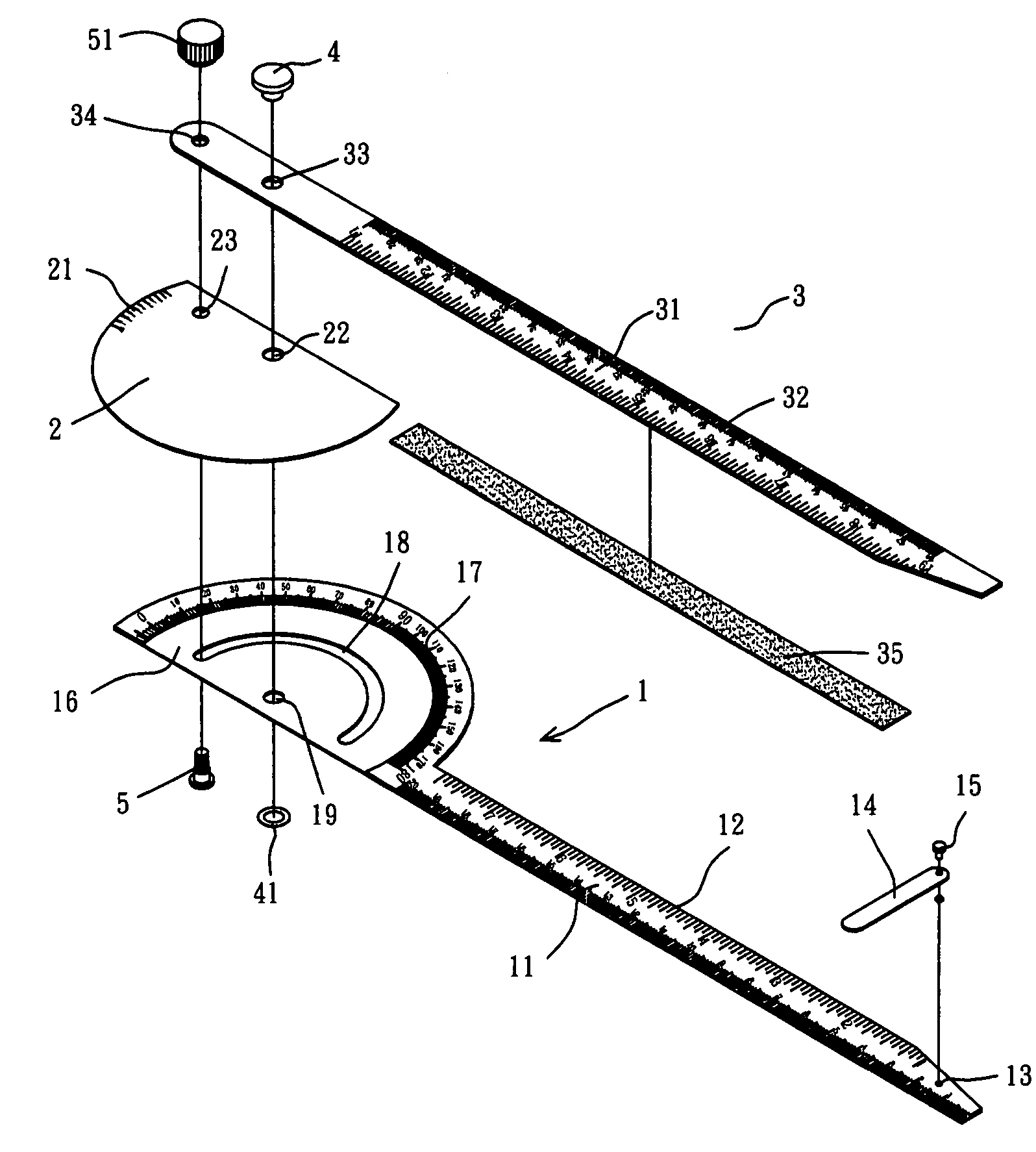
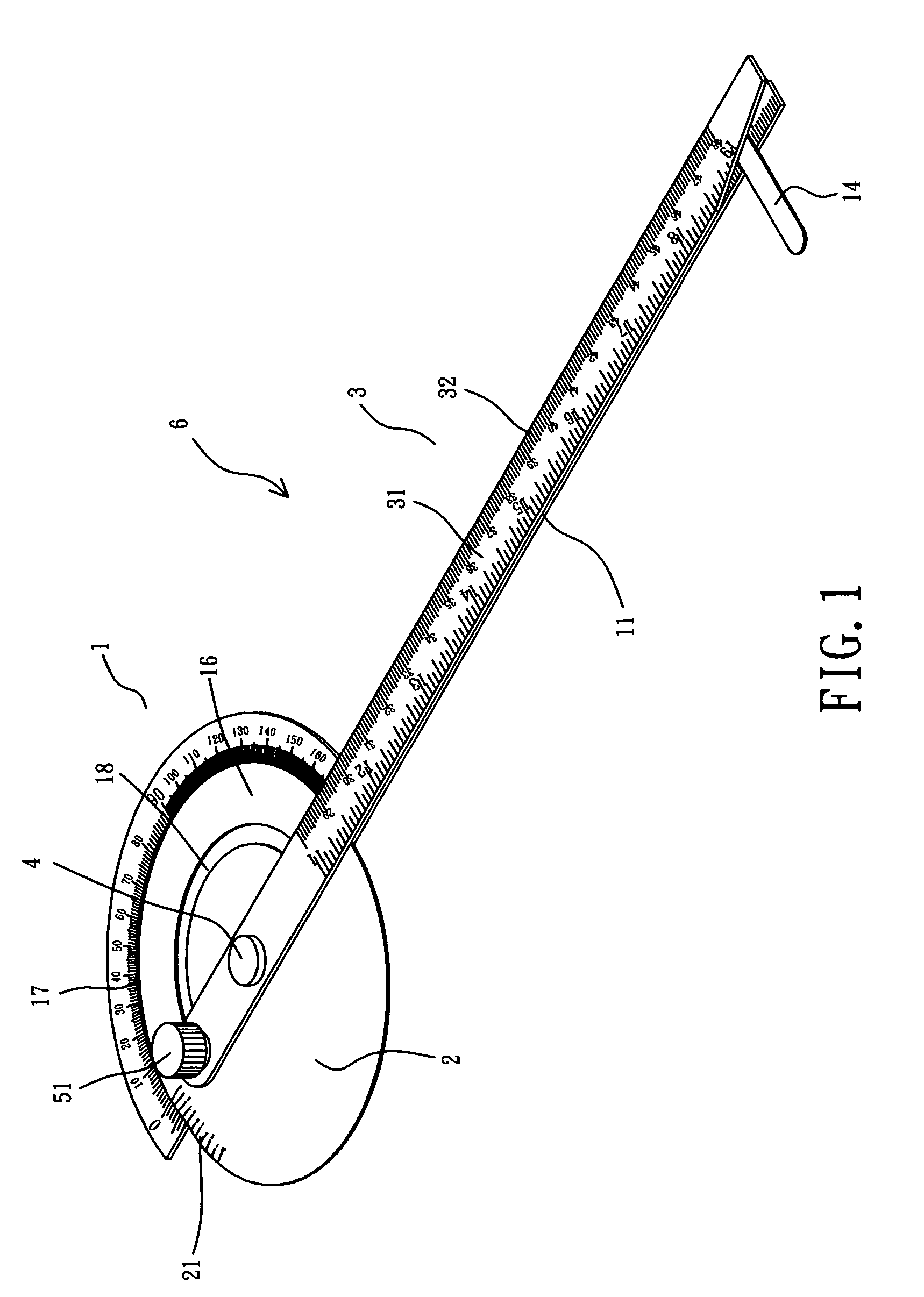
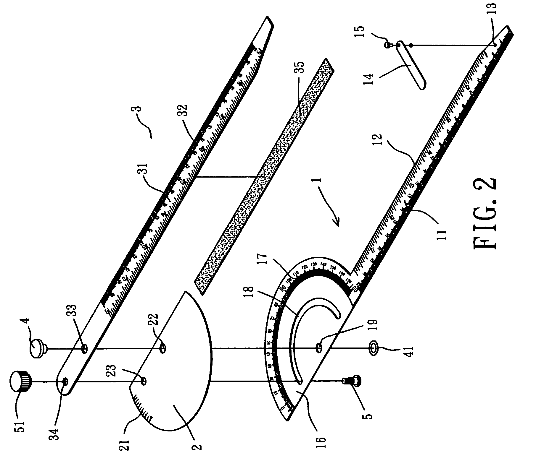
[0027]Referring to the drawings and initially to FIGS. 1–4, a protractor and ruler combination 6 in accordance with the preferred embodiment of the present invention comprises a main ruler 1, a secondary ruler 2, and an auxiliary ruler 3.
[0028]The main ruler 1 has a first side connected to a second side. The first side is formed with a protractor 16 having a plurality of scales 17. The second side is formed with a ruler section 11 having a plurality of scales 12.
[0029]The ruler section 11 of the main ruler 1 has a distal end formed with a fixing hole 13. The, protractor and ruler combination 6 further comprises a support member 14 pivotally mounted on the ruler section 11 of the main ruler 1, and a pivot shaft 15 extended through an end of the support member 14 and fixed in the fixing hole 13 of the ruler section 11.
[0030]The protractor 16 of the main ruler 1 has a center formed with a through hole 19 and has a periphery formed with an arc-shaped guide slot 18.
[0031]The secondary ru...
PUM
 Abstract
Description
Claims
Application Information