
Two-cycle combustion engine with air scavenging system

a two-cycle combustion engine and air scavenging technology, which is applied in the direction of combustion engines, machines/engines, feed systems, etc., can solve the problems of reducing productivity and increasing manufacturing costs, the cost of dies or molds of complicated shapes is generally high, and the two-cycle combustion engine is generally expensive. , to achieve the effect of simplifying the shape, reducing the cost and simplifying the shap

Active Publication Date: 2005-12-27
KAWASAKI MOTORS LTD
View PDF5 Cites 32 Cited by
  • Summary
  • Abstract
  • Description
  • Claims
  • Application Information

AI Technical Summary

Benefits of technology

[0009]Accordingly, the present invention is intended to provide an improved two-cycle combustion engine having an air scavenging system, in which scavenge passage necessary to accomplish the air scavenging can be formed with the use of dies or molds of a simplified structure and in which the number of component parts and the number of assembling steps can also be reduced with the manufacturing cost reduced consequently.

Problems solved by technology

Because of this, the number of component parts such as the connecting tube and clamps as well as the number of assembling steps increases, resulting in reduction in productivity and increase in manufacturing cost.
Considering that the dies or molds of a complicated shape are generally expensive, the two-cycle combustion engine disclosed in the above mentioned patent publication obviously requires increase of the manufacturing cost.

Method used


Image

  • Two-cycle combustion engine with air scavenging system
  • Two-cycle combustion engine with air scavenging system
  • Two-cycle combustion engine with air scavenging system

Examples


Embodiment Construction

[0037]Hereinafter, preferred embodiments of the present invention will be described in detail with reference to the accompanying drawings.

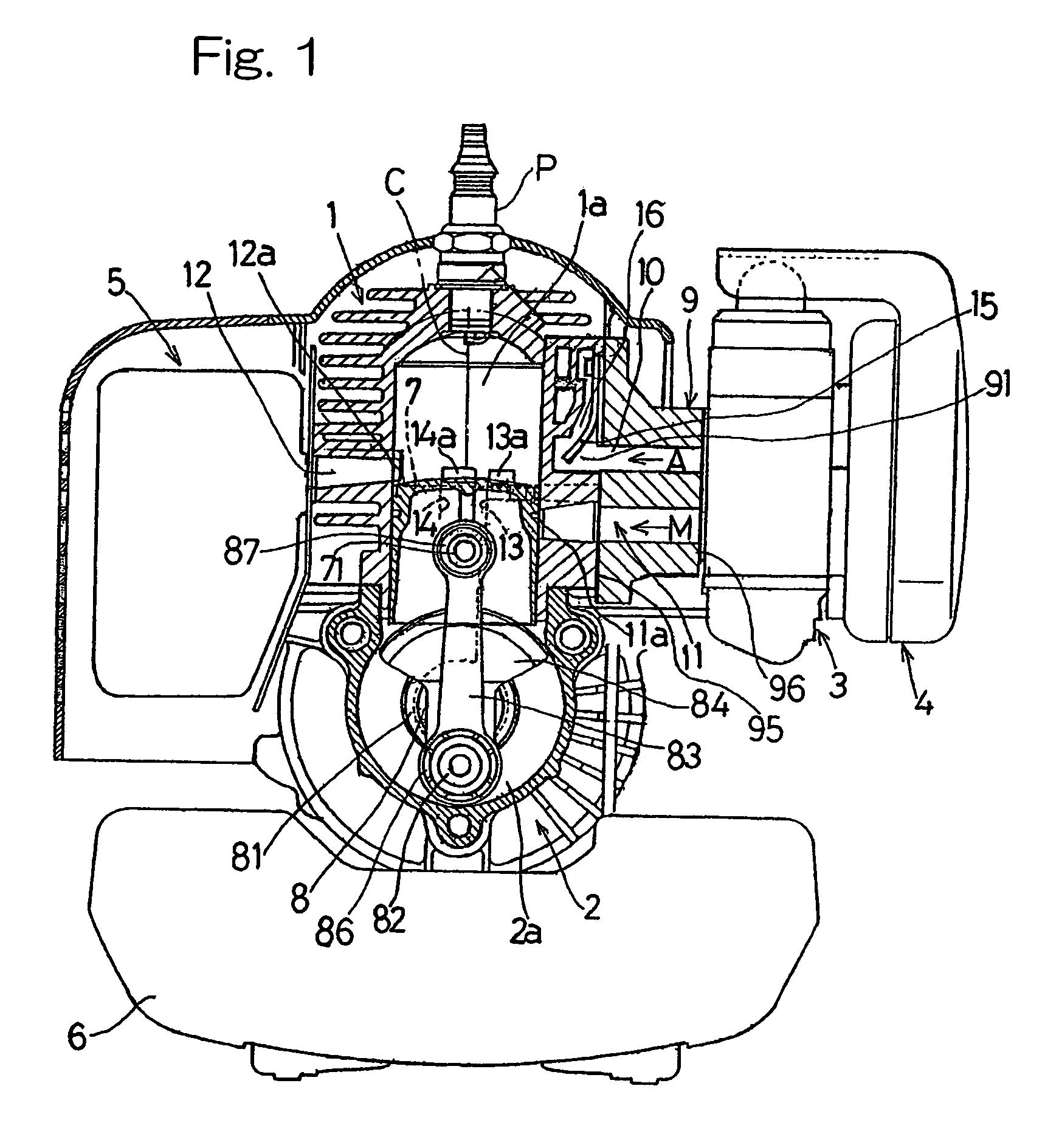
[0038]Referring first to FIG. 1, the two-cycle internal combustion engine shown therein includes an engine cylinder block 1 having a combustion chamber 1a defined therein and an ignition plug P mounted atop the cylinder block 1, and a crankcase 2 on which the cylinder block 1 is fixedly mounted. The cylinder block 1 and the crankcase 2 are made of a metallic material such as aluminum and are formed by a metal casting process in a manner well known to those skilled in the art. The cylinder bore in the cylinder block 1 accommodates therein a piston 7 for reciprocating movement in a direction axially thereof, which piston 7 cooperates with the cylinder bore to define a capacity-variable combustion chamber 1a.

[0039]A carburetor 3 and an air cleaner unit 4, forming respective parts of an air intake system of the two-cycle internal combustion engine ar...


PUM


Abstract

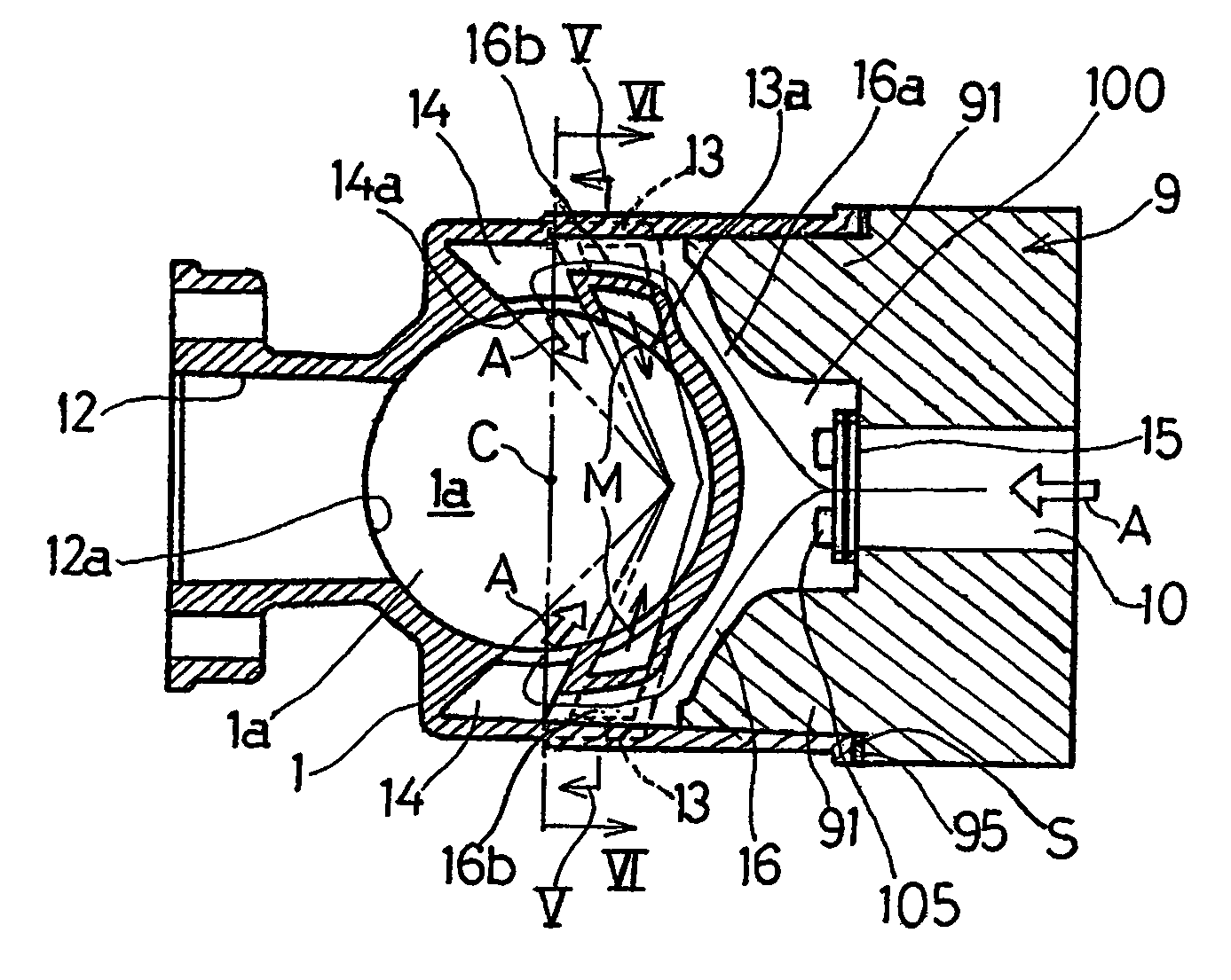
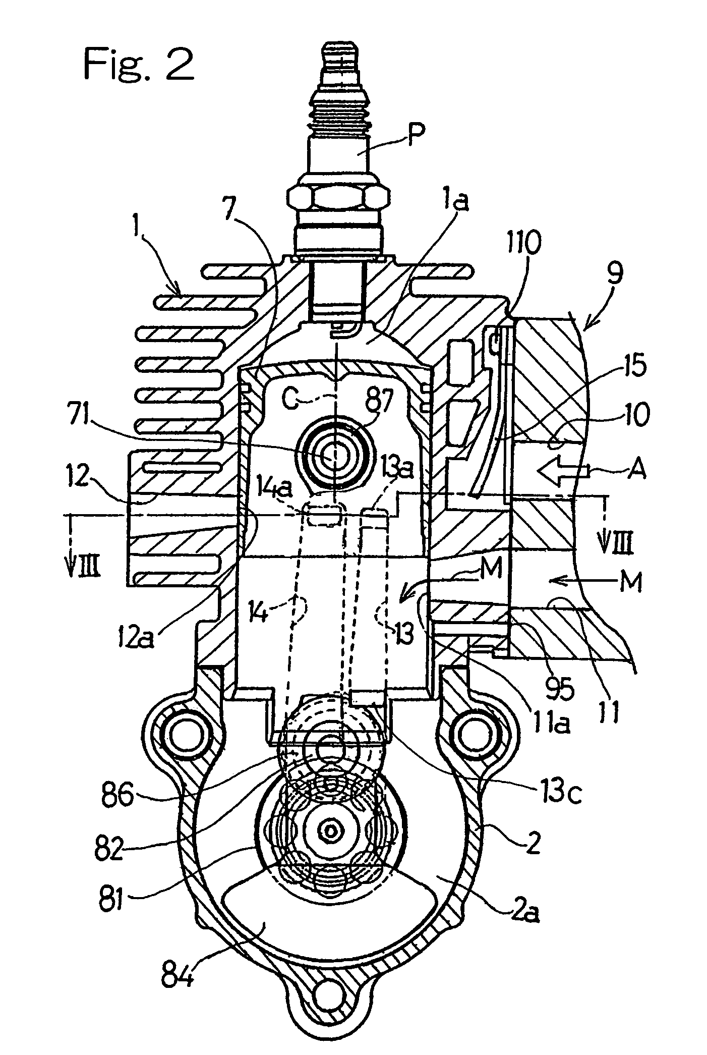
The two-cycle combustion engine includes a first scavenge passage (12) for communicating directly between a combustion chamber (1a) and a crank chamber (2a), a second scavenge passage (14) for communicating the combustion chamber (1a) and the crank chamber (2a) through a bearing (81) for a crankshaft (8), an air supply passage (10) for introducing air (A) into the second scavenge passage (14), a reed valve (15) provided in the air supply passage (10), and an air-fuel mixture supply passage (11) for introducing an air-fuel mixture (M) into the crank chamber (2a). The second scavenge passage (14) is positioned at a location nearer to an exhaust port (12a) than the first scavenge passage (13). An air introducing passage (16) is formed in an cylinder block (1) so as to communicate the air supply passage (10) with the second scavenge passage (14) by way of a radially outer portion of the first scavenge passage (13).

Description

CROSS-REFERENCE TO THE RELATED APPLICATIONS[0001]United State Patent Application entitled “Two-cycle Combustion Engine” and filed even day herewith in the United States with the Convention priorities based on the Japanese Patent Application Nos. 2003-163108 filed on Jun. 9, 2003 and 2003-177509 filed on Jun. 23, 2003, the filing number of which has not yet been allocated.BACKGROUND OF THE INVENTION[0002]1. Field of the Invention[0003]The present invention generally relates to a two-cycle combustion engine of an air scavenging type suitable for use as a power plant for a compact work machine such as, for example, a bush cutter or mowing machine.[0004]2. Description of the Prior Art[0005]The two-cycle combustion engine of the type referred to above has hitherto been well known, in which prior to the air-fuel mixture introduced into the combustion chamber to scavenge the latter, preparatory scavenging with air takes place to suppress a blow-off of a portion of the air-fuel mixture outw...

Claims


Application Information

Patent Timeline
Patent Type & Authority Patents(United States)
IPC IPC(8): F02B25/16F02M15/06F02B25/20F02B25/22F02B33/04F02B33/30
CPCF02B25/16F02B25/20F02B33/04F02B33/30
Inventor YUASA, TSUNEYOSHIKOBAYASHI, MASANORI
Owner KAWASAKI MOTORS LTD
Learn More