Door mirror set plate

a technology for door mirrors and set plates, applied in the field of car door mirrors, can solve the problems of insufficient strength of the support shaft, inability to resist stress concentration, and inability to meet the needs of the user, and achieve the effect of enhancing strength and functionality

Inactive Publication Date: 2005-12-27
MURAKAMI CORP
View PDF2 Cites 17 Cited by
  • Summary
  • Abstract
  • Description
  • Claims
  • Application Information

AI Technical Summary

Benefits of technology

[0010]It is therefore an object of the present invention to provide a door mirror set plate which solves the above-mentioned problems and excels in strength and functionality.
[0012]Since the door mirror set plate according to the present invention provides the curved surface section at the bottom of the support shaft, it is possible to relieve stress concentration on a junction between the support shaft and the base plate and improve the durability. Since the curved surface section is provided below the top surface of the base plate, it is also possible to prevent the curved surface section from appearing above the top surface of the base plate. The curved surface section can be provided in a narrow space without increasing an external diameter of the support shaft.
[0013]On the door mirror set plate, it may be preferable to provide a flat section which is formed at an outside periphery of the support shaft base on the top surface of the base plate at the same level as the top surface of the base plate and which connects between the external surface of the support shaft and the top surface of the base plate by crossing the curved surface section. This makes it possible to use the flat section to support the bottom surface of the thrust washer provided on the support shaft base. Accordingly, the thrust washer can be supported at its internal diameter side without being disposed in the curved surface section, ensuring smooth rotation of the door mirror body.
[0015]When the conducting wire is inserted into the wiring hole for the door mirror set plate, the tip of the covering touches the step section. The step section can be used for positioning the conducting wire. That is to say, the conducting wire can be inserted into the wiring hole until the covering touches the step section. This makes it possible to control the amount of inserting the conducting wire independently of workers' different skills and always keeps the insertion position of the conducting wire constant.
[0017]The door mirror set plate is configured to integrally form the stopper and the positioning protrusion both of which relate to rotative movements of the door mirror body. Accordingly, the positioning protrusion can supplement the strength of the stopper, making it possible to improve the durability. Since the stopper and the positioning protrusion are integrated, the part shape is simplified and the space saving efficiency improves.

Problems solved by technology

With regard to using a synthetic resin for the set plate as a supporting member for the door mirror body, there have been the following problems.
Firstly, if the support shaft as well as the set plate is made of synthetic resin, the base of the support shaft produces insufficient strength.
While the stress concentrates on the base of the support shaft, the synthetic resin lacks the member strength against the stress concentration.
However, increasing the diameter of the support shaft is undesirable because of limitations on the set plate size and relation with the other parts.
For this reason, it has been difficult to form the curved surface section for relieving the stress at the support shaft base and has caused insufficient strength to the support shaft.
Secondly, a thrust washer attached to the support shaft base causes the following problem.
If the support shaft base is provided with the curved surface section, however, the thrust washer cannot be placed on a flat surface, preventing smooth rotations of the door mirror body.
Further, the washer diameter increases for the play, disadvantageous to space saving considerations.
Thirdly, there is also the problem of insufficient strength concerning a mechanism to restrict operations of the door mirror body.
The set plate, if made of synthetic resin, causes insufficient strength to the stopper protrusion that touches the groove end and restricts rotative movement of the door mirror body.
There has also been a problem of complicating parts shapes and degrading the space saving efficiency.
The conventional set plate also has a problem with positioning of a conducting wire to be inserted into the support shaft.
Since the conventional set plate uses a same hollow inside the support shaft, however, it is difficult to determine how long the conducting wire is inserted.

Method used


Image

  • Door mirror set plate
  • Door mirror set plate
  • Door mirror set plate

Examples


Embodiment Construction

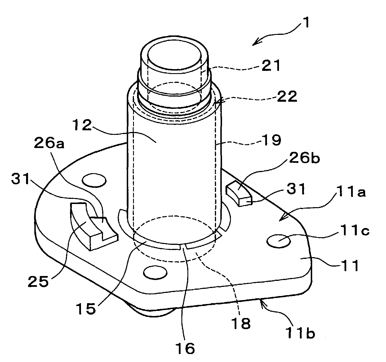
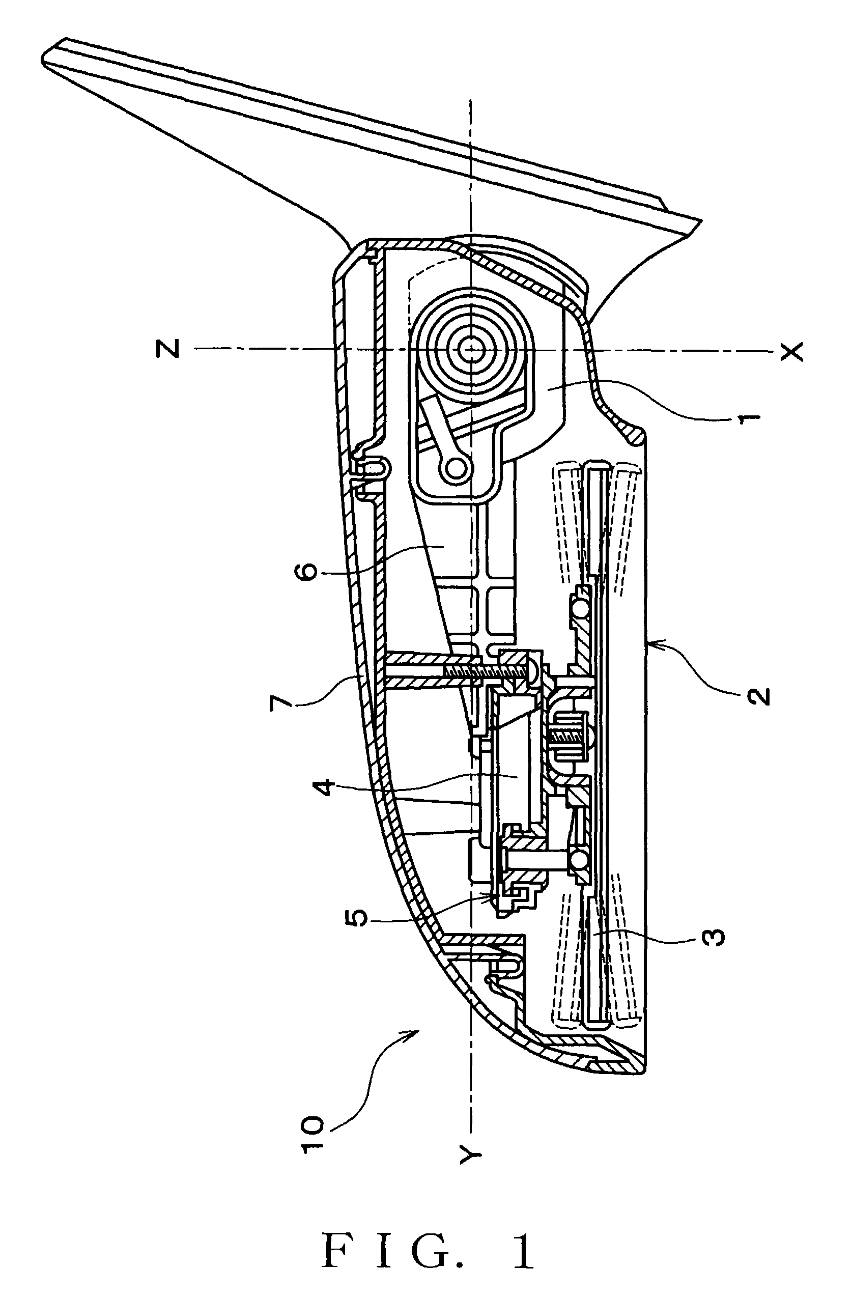
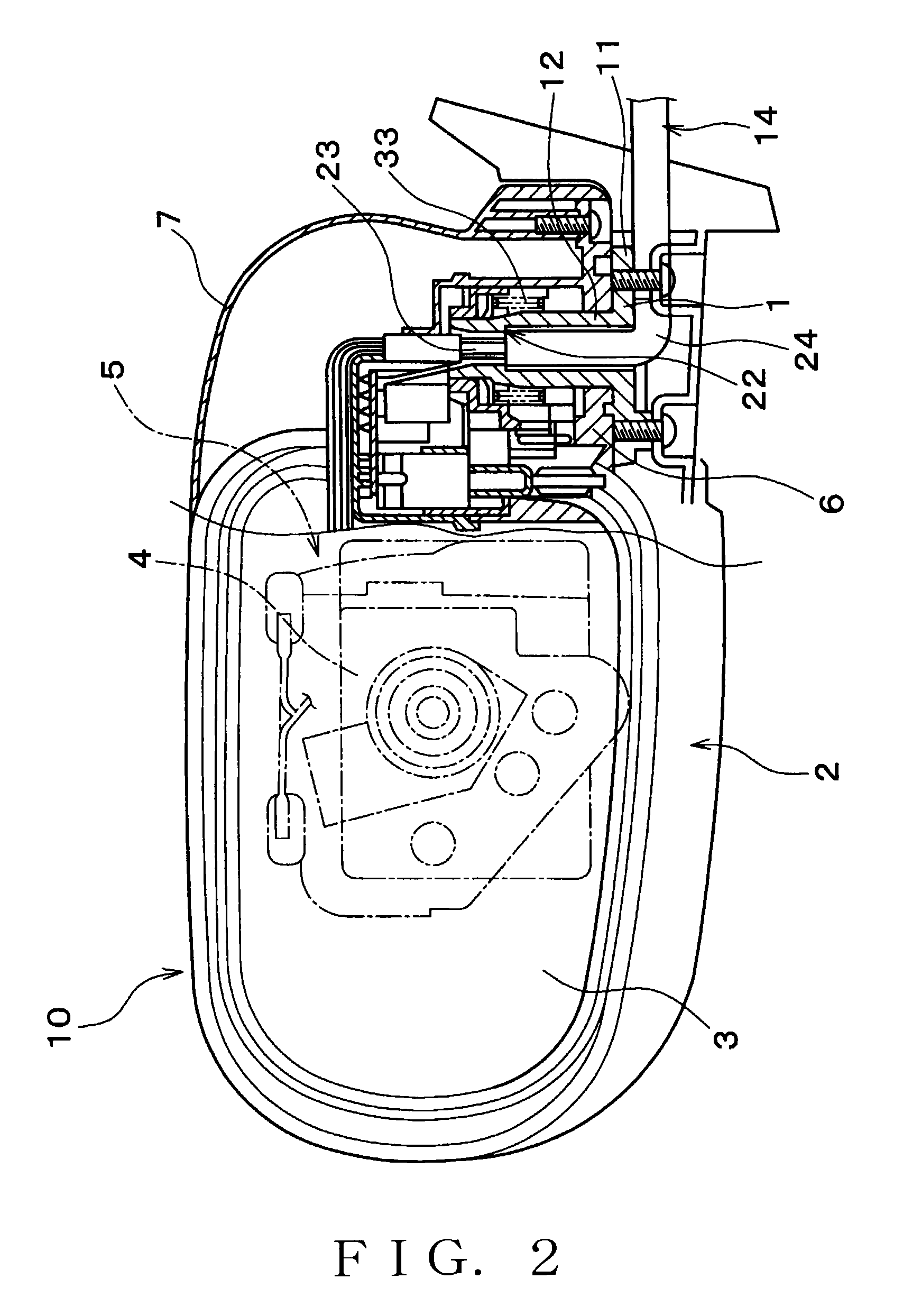
[0031]An embodiment of the present invention will be described in further detail with reference to the accompanying drawings. As shown in FIG. 1, a door mirror 10 comprises a door mirror set plate 1 (hereafter abbreviated to a set plate 1) and a door mirror body 2. The set plate 1 is fixed to a body side of the car. The door mirror body 2 is rotatively attached onto the set plate 1. The door mirror body 2 further comprises a body 5 and a bracket 6. The body 5 contains a drive unit 4 comprising a mirror plate 3, a motor, and the like. The bracket 6 holds the body 5 and is rotatively attached to the set plate 1.

[0032]The door mirror 10 is a so-called electric retractable apparatus. The door mirror body 2 can rotatively move approximately 180 degrees from a retracted position X to a safety position Z via a neutral position Y around the set plate 1 by means of the drive unit 4. The drive unit 4 allows angles of the mirror plate 3 to be controlled remotely. The door mirror body 2 is exte...


PUM


Abstract

A door mirror set plate is formed of synthetic resin. On a base plate, a support shaft is vertically provided to rotatively support a door mirror body. A curved surface section is embedded at an outside periphery of a base of the support shaft. A flat section is formed to support a thrust washer so as to cross the curved surface section. Inside the support shaft, there is formed a wiring hole provided with a large diameter section, a small diameter section, and a step section. When a conducting wire is inserted into the wiring hole, the tip of a covering touches the step section for positioning. A stopper and a positioning protrusion are integrally formed on a base plate top surface. The stopper restricts rotational angles of the door mirror body. The positioning protrusion holds the door mirror body at a neutral position.

Description

BACKGROUND OF THE INVENTION[0001]1. Field of the Invention[0002]The present invention relates to a car door mirror and more particularly to a set plate for rotatably supporting a door mirror body that stores a mirror plate.[0003]2. Related Art Statement[0004]In accordance with recent demands for weight saving of a car body and cost saving, various metal parts have been replaced by synthetic resins. A door mirror is not an exception. Synthetic resins are extensively used for not only the door mirror body, but also a set plate that supports the door mirror body. The set plate comprises a base plate to be attached to a car door and a support shaft for rotatably supporting the door mirror body. The set plate is conventionally made of zinc die cast metal. If the base plate and the support shaft are integrally molded out of synthetic resin, this would enable a drastic reduction in weight compared to a metal set plate.[0005]With regard to using a synthetic resin for the set plate as a supp...

Claims


Application Information

Patent Timeline
Patent Type & Authority Patents(United States)
IPC IPC(8): B60R1/074
CPCB60R1/074
Inventor ICHIKAWA, OSAMU
Owner MURAKAMI CORP
Why Eureka
Try Eureka