Master cylinder and method of manufacturing the same

a technology of master cylinder and cylinder body, which is applied in the direction of rotary clutches, fluid couplings, brake systems, etc., can solve the problems of more bite in the cup seal, the intrusion l of the deformed portion is considered large, etc., and achieves the effect of preventing the damage of the cup seal and relieving the stress concentration

Inactive Publication Date: 2011-01-11
HITACHI LTD
View PDF9 Cites 1 Cited by
  • Summary
  • Abstract
  • Description
  • Claims
  • Application Information

AI Technical Summary

Benefits of technology

[0004]An objective of the present invention is to provide a master cylinder capable of controlling an increase in an amount of intrusion of a cup seal while relieving a stress concentration therein to thereby prevent a cup seal from being damaged, and a manufacturing method of the master cylinder.

Problems solved by technology

However, the change involved a problem that, by increasing the radius of the chamfered portion 105 from R1 to R2, locations defining both ends of the circular arc of the chamfered portion 105 are shifted away from A1, B1 to A2, B2, respectively, resulting in a considerable increase in an intrusion L of the deformed portion 106, as shown in FIG. 12B, which is likely to causes more bite in the cup seal.

Method used


Image

  • Master cylinder and method of manufacturing the same
  • Master cylinder and method of manufacturing the same
  • Master cylinder and method of manufacturing the same

Examples


first embodiment

[0034]An explanation will be given of a master cylinder and a method for manufacturing the master cylinder according to the present invention in reference to FIG. 1 through FIG. 6.

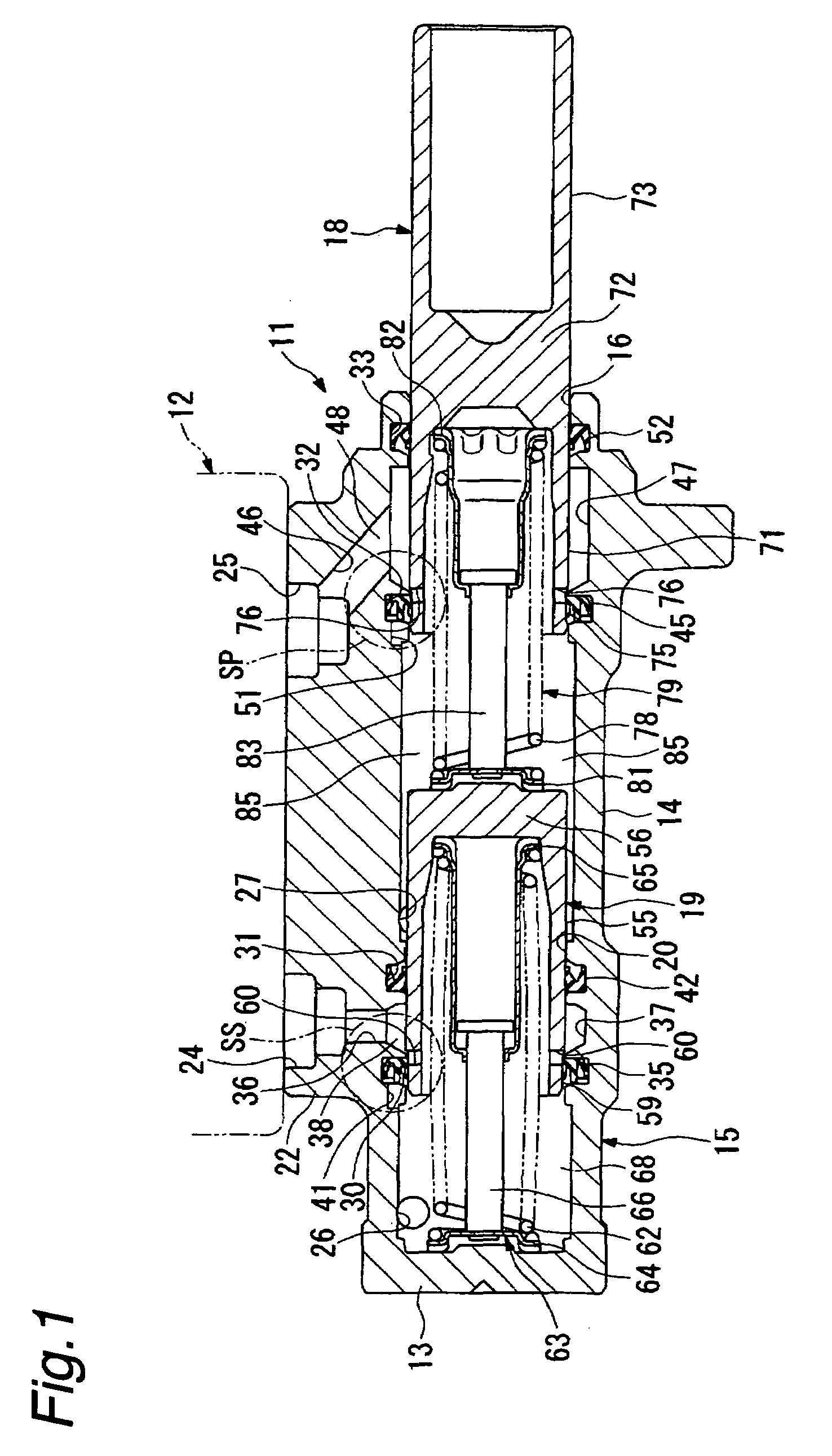
[0035]A notation 11 in FIG. 1 designates a master cylinder of the first embodiment for generating a brake hydraulic pressure with a force according to an operation amount of a brake pedal introduced via a brake booster; though not shown, wherein a reservoir 12 for charging and discharging a brake fluid is mounted to an upper portion of the master cylinder 11.

[0036]The master cylinder 11 is of a tandem type, which comprises a cylinder main body 15 formed by processing a single mass of material into a bottomed cylinder shape having a bottom portion 13 and a cylinder portion 14, said cylinder main body 15 being arranged in a vehicle along a lateral direction, a primary piston (piston) 18 slidably inserted into the cylinder main body 15 in an opening portion 16 side thereof, and a secondary piston (piston) 19 ...

second embodiment

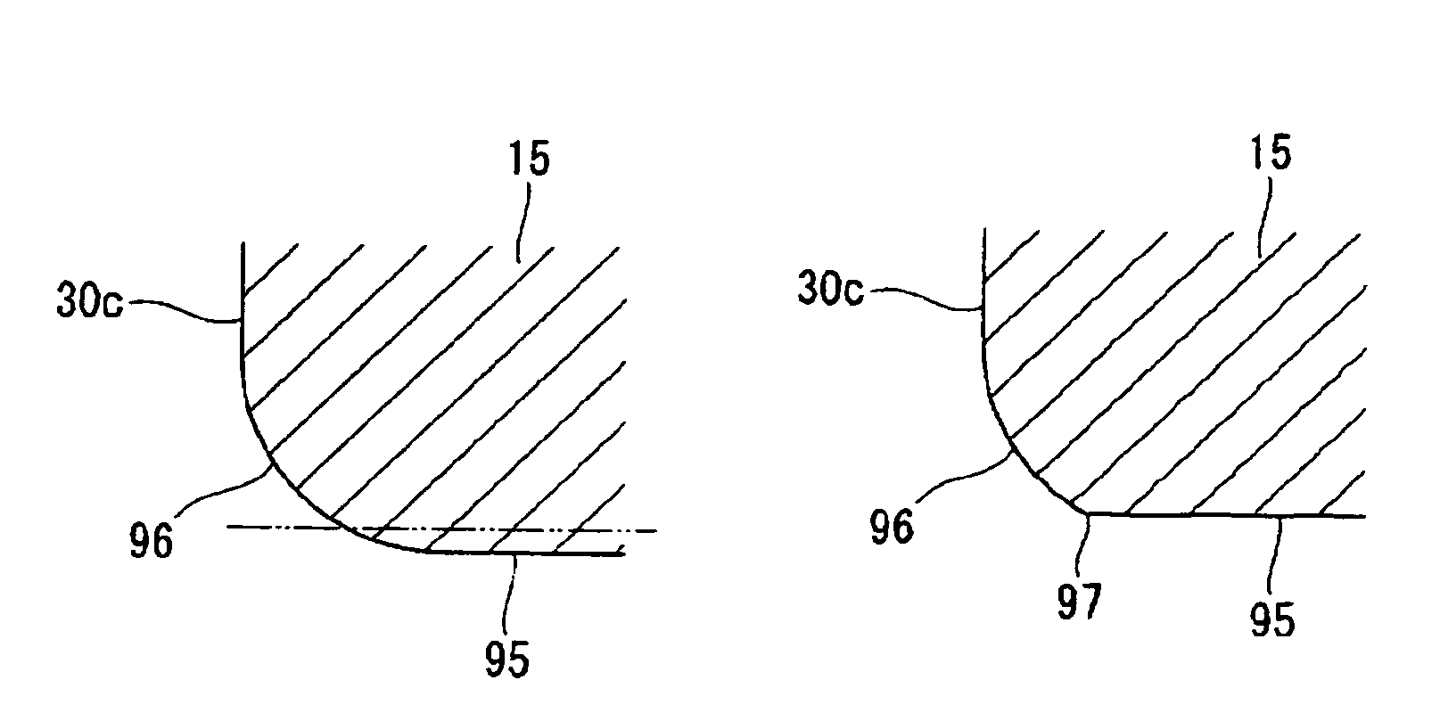
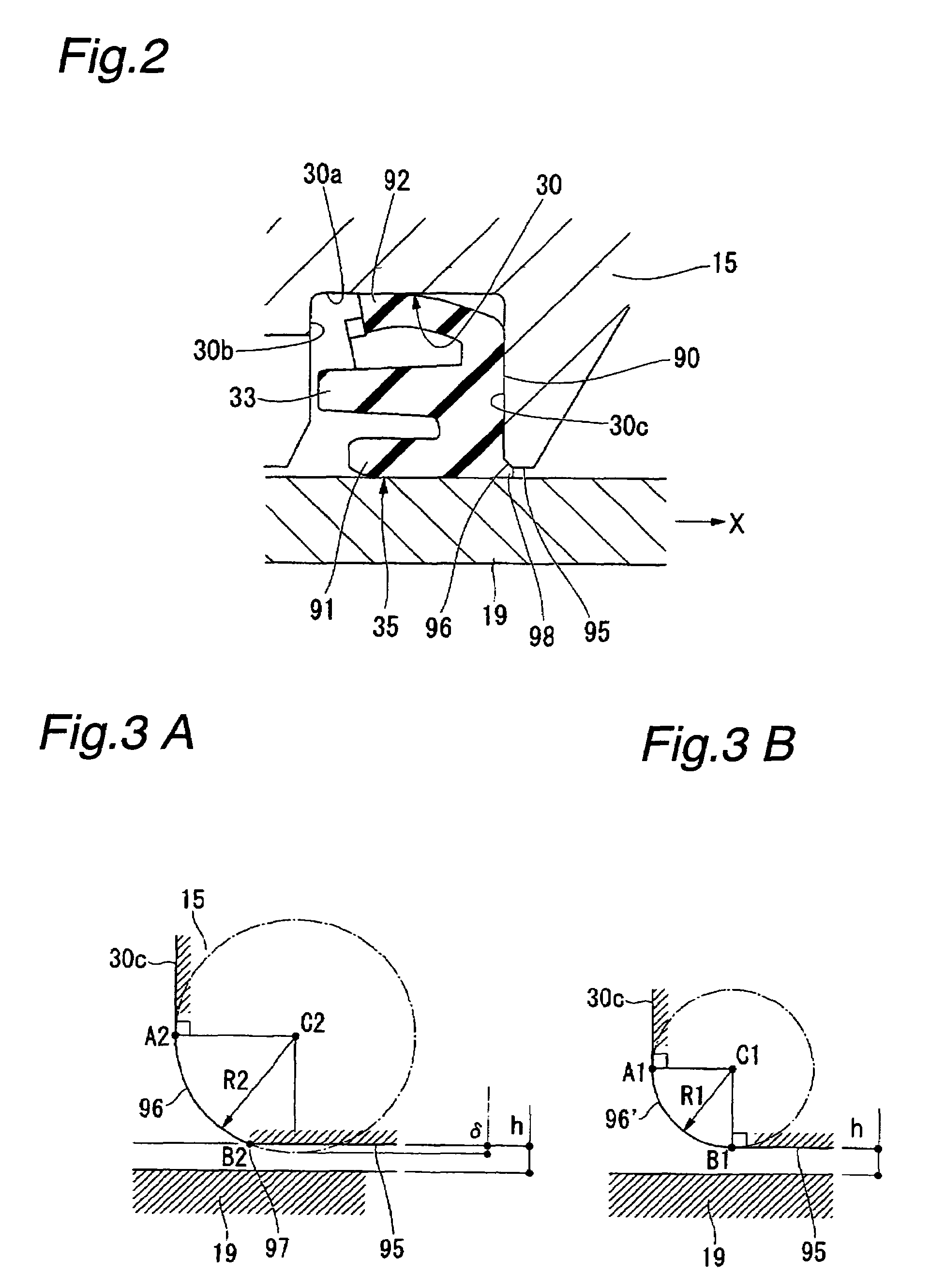
[0074] the secondary side sealing structure SS is provided with a chamfered portion 96 having a curved shape in a cross-section taken along the diameter direction of the cylinder main body 15 between the annular wall 30c and the cylinder wall 95, as shown in FIG. 7, wherein the chamfered portion 96 has a shape of an elliptic arc, a long axis of which extends along a radius direction of the cylinder main body 15.

[0075]The chamfered portion 96 is configured such that one end portion A2 is formed continuously so that a tangent thereof may be in line with a wall surface of the annular wall 30c, while the other end portion B2 is formed so as to constitute a flexed portion 97 in combination with the cylinder wall 95.

[0076]According to the master cylinder 11 of the second embodiment described above, in the secondary side sealing structure SS, since the chamfered portion 96 having a shape of an elliptic arc and formed between the annular wall 30c behind the cup seal 35 and the cylinder wall...

third embodiment

[0081] the secondary side sealing structure SS is provided with a chamfered portion 96 having a curved shape in a cross-section taken along the diameter direction of the cylinder main body 15 between the annular wall 30c and the cylinder wall 95, wherein the chamfered portion 96 has a shape of a parabola, and is connected to the annular wall 30c at a vertex of the parabola shape.

[0082]The chamfered portion 96 is configured such that one end portion A2 is formed continuously so that a tangent thereof may be in line with a wall surface of the annular wall 30c, while the other end portion B2 is formed so as to constitute a flexed portion 97 in combination with the cylinder wall 95.

[0083]According to the master cylinder 11 of the third embodiment described above, in the secondary side sealing structure SS, since the chamfered portion 96 having a shape of a parabola and formed between the annular wall 30c behind the cup seal 35 and the cylinder wall 95 to which the secondary piston 19 is...


PUM

PropertyMeasurementUnit
diameteraaaaaaaaaa
radius of curvatureaaaaaaaaaa
shapeaaaaaaaaaa

Abstract

An object of the present invention is to provide a master cylinder capable of controlling an increase in an intruding amount of a cup seal while relieving a stress concentration therein to thereby prevent the cup seal from being damaged. Provided is a master cylinder in which a piston is moved in slidable contact with an inner circumference of a cup seal held in a cylinder main body so as to pressurize a brake fluid in a pressure chamber formed of the piston and the cylinder main body, wherein an annular wall configured integrally with the cylinder main body is provided behind the cup seal. Further, a chamfered portion having a curved shape in a cross-section taken along a diameter direction of the cylinder main body is provided between the annular wall and a cylinder wall to which the piston is facing. One end of the chamfered portion is formed continuously so that a tangent thereto is in line with the annular wall, and the other end of the chamfered portion is formed to constitute a flexed portion in combination with the cylinder wall.

Description

BACKGROUND OF THE INVENTION[0001]The present invention relates to a master cylinder for supplying a brake fluid to a brake system of a vehicle and a method of manufacturing the master cylinder.[0002]As a master cylinder for supplying a brake fluid to a brake system of a vehicle, for example, as described in Japanese Patent Publication No. 2006-123879, there is provided a constitution in which a piston is operatively provided on an inner circumference of a cup seal held in a seal groove of a cylinder main body so as to be slidable therein, and a brake fluid in a pressure chamber formed by the piston and the cylinder main body is pressurized by the sliding movement of the piston so as to be supplied to the brake system. This type of master cylinder has an annular wall 102 in a cylinder main body 100, which is a part of a seal groove and is located behind a cup seal 101, and a corner portion provided between the annular wall 102 and a cylinder wall 104 facing an outer circumference sur...

Claims


Application Information

Patent Timeline
Patent Type & Authority Patents(United States)
IPC IPC(8): B60T11/16F15B7/08
CPCB60T11/236F15B7/00Y10T29/49236
Inventor OKADA, HIROKIKOSHIMIZU, NAGANORI
Owner HITACHI LTD
Why Eureka
Try Eureka