Power transmission system

a transmission system and power technology, applied in the direction of gearing, couplings, hoisting equipment, etc., can solve the problems of deformation or even breakage, deformation of the base of the gate mark remaining after integral molding, and excessive plastic pulleys, so as to prevent stress concentration and ensure durability.

Inactive Publication Date: 2011-04-12
DENSO CORP
View PDF22 Cites 2 Cited by
  • Summary
  • Abstract
  • Description
  • Claims
  • Application Information

AI Technical Summary

Benefits of technology

[0008]An object of the present invention, in view of this problem, is to provide a power transmission system in which a hub and a torque transmission elastic member are integrally molded where the gate marks remaining after integral molding are shaped to prevent stress concentration and where more superior durability is achieved.
[0009]The present invention achieves the above object by provision of the following power transmission system. That is, it provides a power transmission system provides with a pulley (1) rotatably attached to a casing (4) and a hub (2) provided at a front end of a shaft (3) projecting to the outside from the casing (4) and rotating integrally with the shaft and transmitting power from the pulley (1) to the shaft (3), wherein the hub (2) is comprised of an inner hub (2c) fastened to the shaft (3), an outer ring (2b) arranged at an outer circumference side from the inner hub (2c), and a torque transmission elastic member (2d, 2a) integrally molded together with the inner hub (2c), and the outer ring (2b) and a gate mark (2f, 2g, 2h) consisting of a mark of an injection gate used for the integral molding is formed at the position of the outer ring (2b) or at the outer circumference side from the outer ring (2b). Due to this, it is possible to ease the stress concentration at the gate mark.
[0010]Preferably, the torque transmission elastic member (2d, 2a) is comprised of a cylindrical part (2d) between the inner hub (2c) and the outer ring (2b) and a hub side relief section (2a) provided at the outer circumference of the outer ring (2b), and the pulley (1) has a pulley side relief section (1a) engaging with the hub side relief section (2a). Due to this, it is possible to relieve the stress concentration at the gate mark formed at the hub in a power transmission system where the hub and pulley are engaged.
[0011]Preferably, the gate mark (2f) is formed at the end of the outer ring (2b). Therefore, the radius of curvature of the base of the gate mark can be made larger. Further, since the gate mark is formed near the outer ring, the resistance to stress increases.
[0012]Preferably, the gate mark (2g) is formed at the outer circumference of the outer ring (2b). Since the gate mark is formed near the outer ring, the resistance to stress increases.
[0013]Preferably, the gate mark (2h) is formed at the side surface of the hub side relief section (2a). Since the gate mark is formed at the outer circumference of the hub, the stress on the gate mark can be reduced.

Problems solved by technology

However, in the prior art, there was the problem that excess torque or torque fluctuations caused the projection of the outside ring of the hub and recess of the pulley to directly contact and caused the recess of the plastic pulley, which is inferior to the projection of the outside ring in strength and abrasion resistance, to end up being abnormally abraded.
However, the bases of the gate marks remaining after integral molding have small radii of curvature.
If a load susceptible to torque fluctuations is received frequently over a long time, stress concentrates near the gate marks possibly leading to deformation or even breakage.

Method used


Image

  • Power transmission system
  • Power transmission system
  • Power transmission system

Examples


Embodiment Construction

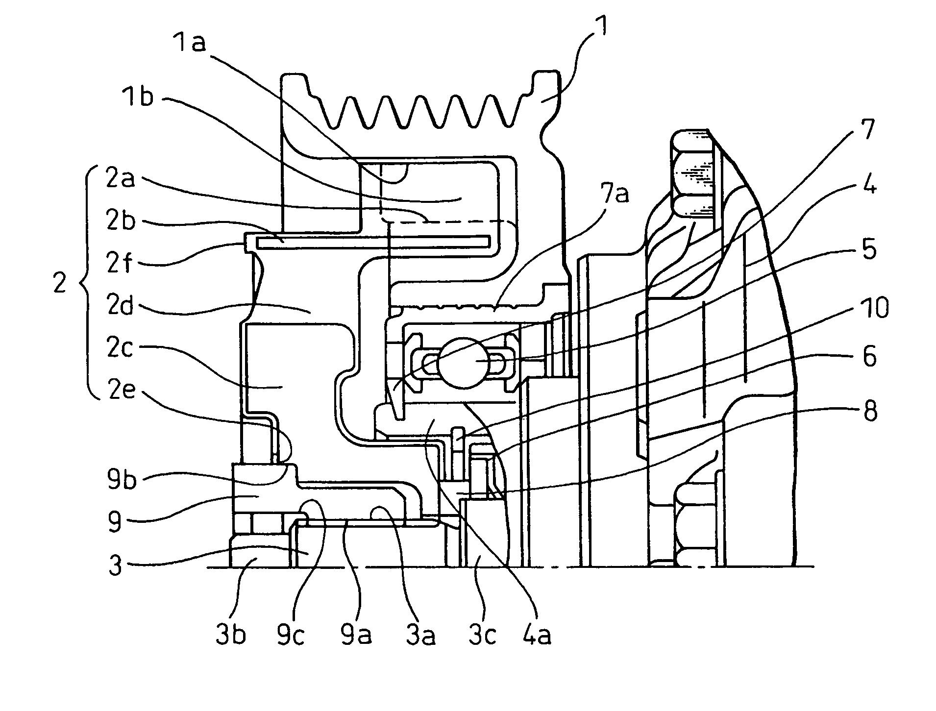
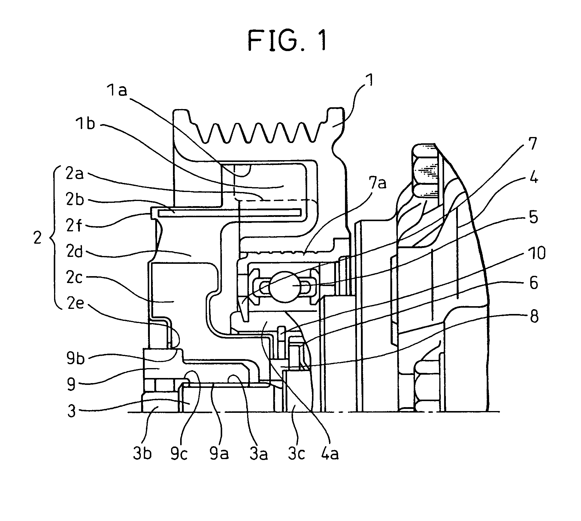
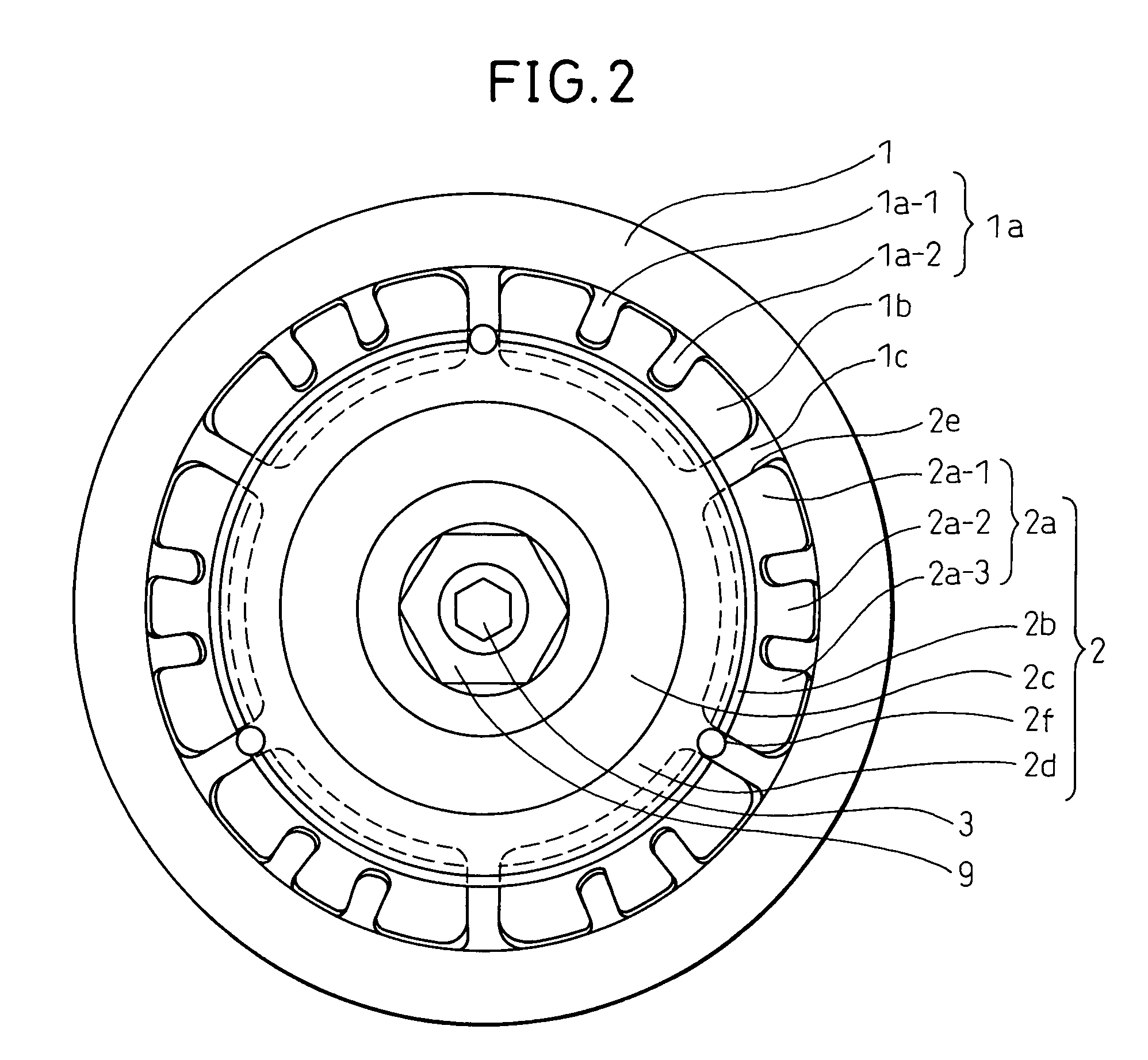
[0023]Below, power transmission systems according to embodiments of the present invention will be explained with reference to the drawings. The power transmission systems according to these embodiments are suitable for being built into compressors of vehicular air-conditioning systems. FIG. 1 is a view showing the cross-section of the top half of a power transmission system according to a first embodiment of the present invention, while FIG. 2 is a front view of a power transmission system of a first embodiment. The power transmission system of this embodiment transmits power (torque) between a pulley 1 as a drive side rotational member obtaining power from an engine or motor and a hub 2 as a driven side rotational member fastened to a shaft 3 of a compressor. The pulley 1 and hub 2 are provided coaxially.

[0024]The pulley 1 is rotatably mounted to a cylindrical boss 4a provided at one end of a casing 4 of the compressor through a bearing 5 and a first snap ring 7 provided with a sle...


PUM


Abstract

A power transmission system including an integrally molded hub and elastic member, where stress is inhibited from concentrating at the gate marks remaining after integral molding. In a pulley driven by a belt, a plastic pulley side relief section 1a provided at a pocket section of the pulley and a plastic hub side relief section provided on an iron outer ring of the hub engaged at the pocket section whereby power is transmitted from the pulley to the shaft. The hub side relief section and outer ring forming parts of the hub, the iron inner hub to be fastened to the shaft, and the plastic cylindrical part are integrally molded so that the gate mark for plastic injection is formed near to or further to the outer circumference of the outer ring.

Description

BACKGROUND OF THE INVENTION[0001]1. Field of the Invention[0002]The present invention relates to a power transmission system having a torque transmission elastic member, specifically relates to a power transmission system suitable for being built into a compressor of a vehicular air-conditioning system.[0003]2. Description of the Related Art[0004]For example, in a vehicular air-conditioning system, as a power transmission system transmitting power from an engine, motor, or other external power source to a compressor forming part of a refrigeration cycle, a power transmission system not having an electromagnetic clutch mechanism, but having a torque limiter is being used. This power transmission system transmits power between a pulley driven by an external power source and a hub fixed to a shaft of the compressor. The hub is provided with a rubber or other damper attenuation mechanism and is arranged coaxially with a pulley. In the past, the pulley and hub were fastened together usin...

Claims


Application Information

Patent Timeline
Patent Type & Authority Patents(United States)
IPC IPC(8): F16D9/00F16H9/00
CPCF16D3/68F16H55/36F16H2055/366Y10S474/902
Inventor TADA, YOSHIKINOSAKA, MICHIYASUTABUCHI, YASUOKAMIYA, TAKUSHISUZUKI, TAKAYUKI
Owner DENSO CORP
Why Eureka
Try Eureka