Piezoelectric device, liquid discharging head, and liquid discharging apparatus

a technology of liquid discharging head and piezoelectric device, which is applied in piezoelectric/electrostrictive/magnetostrictive devices, mechanical vibration separation, printing, etc., can solve the problems of damage to piezoelectric devices, likely etc., to suppress unnecessary deformation of diaphragm accompanying stretching/contracting of stacked materials, suppress generation of cracks in diaphragms, and suppress generation

Inactive Publication Date: 2018-11-29
SEIKO EPSON CORP
View PDF0 Cites 2 Cited by
  • Summary
  • Abstract
  • Description
  • Claims
  • Application Information

AI Technical Summary

Benefits of technology

[0005]An advantage of some aspects of the invention is to suppress the generation of a crack in a diaphragm.
[0006]According to an aspect of the invention, there is provided a piezoelectric device including a pressure chamber, a piezoelectric element, and a diaphragm disposed between the pressure chamber and the piezoelectric element. The diaphragm has a crystal plane of an anisotropic single crystal silicon base of which a Poisson's ratio varies according to a direction in the crystal plane. In a vibration region of the diaphragm, which overlaps the pressure chamber in plan view, the Poisson's ratio of the diaphragm in a short axis direction of the smallest rectangle, which includes the vibration region, is included in a range of a minimum value of the Poisson's ratio in the crystal plane inclusive to an average value of the Poisson's ratios in the crystal plane exclusive. According to this configuration, the Poisson's ratio in the short axis direction, which has an effect on stretching / contracting of the diaphragm in a long axis direction, is restricted to be a value that is higher than or equal to the minimum value and is lower than the average value. Therefore, even when the diaphragm is displaced in a direction of stretching due to vibration of the piezoelectric element, a force that the diaphragm contracts in the long axis direction is weak compared to a case where the Poisson's ratio of the diaphragm in the short axis direction is a high value to an extent to exceed the average value. Thus, a contracted amount in the long axis direction becomes smaller. Since the contracted amount in the long axis direction becomes smaller and the force pulling the diaphragm in the long axis direction weakens by making the Poisson's ratio in the short axis direction lower as described above, for example, stress concentration in a portion (for example, an arm portion) of the diaphragm, which contracts in the long axis direction, is also eased. Thus, the generation of a crack in the diaphragm can be suppressed.
[0007]According to another aspect of the invention, there is provided a piezoelectric device including a pressure chamber, a piezoelectric element, and a diaphragm disposed between the pressure chamber and the piezoelectric element. The diaphragm has a crystal plane of an anisotropic single crystal silicon base of which a Poisson's ratio varies according to a direction in the crystal plane. The single crystal silicon base is a base of which the crystal plane is a {100} plane. In a vibration region of the diaphragm, which overlaps the pressure chamber in plan view, the Poisson's ratio of the diaphragm in a short axis direction of the smallest rectangle, which includes the vibration region, is included in a range of a minimum value of the Poisson's ratio in the crystal plane inclusive to 0.18065 exclusive. According to this configuration, a contracted amount of the diaphragm in the long axis direction becomes smaller compared to a case where the Poisson's ratio is a high value to an extent to exceed 0.18065. Therefore, since stress concentration of the portion of the diaphragm, which contracts in the long axis direction, is also eased, the generation of a crack in the diaphragm can be suppressed.

Problems solved by technology

Therefore, even if a direction of the diaphragm is aligned with a direction in the crystal plane considering only a Young's modulus, a crack is likely to be generated in the diaphragm according to a Poisson's ratio in that direction.
Thus, there is a possibility that the piezoelectric device becomes damaged.

Method used


Image

  • Piezoelectric device, liquid discharging head, and liquid discharging apparatus
  • Piezoelectric device, liquid discharging head, and liquid discharging apparatus
  • Piezoelectric device, liquid discharging head, and liquid discharging apparatus

Examples


first embodiment

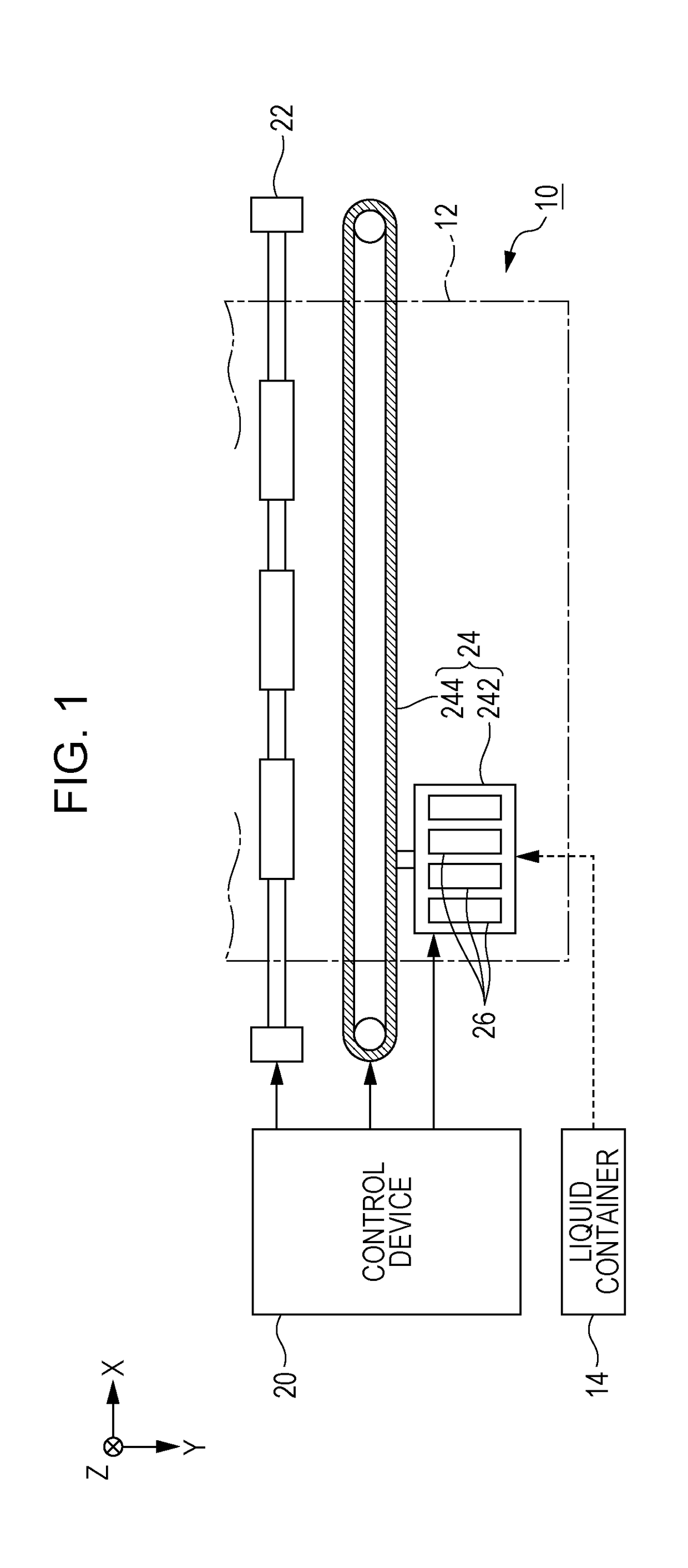
[0038]FIG. 1 is a view illustrating a configuration of a liquid discharging apparatus 10 according to a first embodiment of the invention. The liquid discharging apparatus 10 of the first embodiment is an ink jet printing apparatus that discharges an ink, which is an example of a liquid, onto a medium 12. Although the medium 12 is typical printing paper, any printing target such as a resin film and cloth can be used as the medium 12. As illustrated in FIG. 1, a liquid container 14 storing an ink is fixed to the liquid discharging apparatus 10. For example, a cartridge that is attachable / detachable to / from the liquid discharging apparatus 10, a bag-like ink pack formed of a flexible film, or an ink tank that can be refilled with an ink is used as the liquid container 14. A plurality of types of inks having different colors are stored in the liquid container 14.

[0039]As illustrated in FIG. 1, the liquid discharging apparatus 10 includes a control device 20, a transporting mechanism 22...

second embodiment

[0075]A second embodiment of the invention will be described. In each form to be given as an example below, elements, of which operation and functions are the same as in the first embodiment, will be assigned with the same reference signs used in describing the first embodiment and detailed description of each of the elements will be omitted as appropriate. Although a case where the diaphragm 36 is formed of the single crystal silicon base, of which the crystal plane is the (100) plane, is given as an example in the first embodiment, a case where the diaphragm 36 is formed of a single crystal silicon base, of which the crystal plane is a (110) plane (crystal plane orientation perpendicular to the crystal plane is [110]), will be given as an example in the second embodiment.

[0076]FIG. 7 is a graph showing an example of anisotropy of a Poisson's ratio and a Young's modulus in the (110) plane of the single crystal silicon base of which the crystal plane is the (110) plane. In FIG. 7, a...

third embodiment

[0085]A third embodiment of the invention will be described. A specific configuration example of the piezoelectric elements 37 of the piezoelectric device 39 according to the first embodiment and the second embodiment will be described in the third embodiment. FIG. 8 is a sectional view and a plan view of the enlarged piezoelectric device 39 according to the third embodiment, and corresponds to FIG. 4. The sectional view (view on the upper side of FIG. 8) of FIG. 8 is a view obtained by cutting the piezoelectric device 39 with the XZ-plane, and the plan view (view on the lower side of FIG. 8) of FIG. 8 is a view in which the piezoelectric device 39 is seen from the Z-direction. FIG. 9 is a sectional view of the piezoelectric device 39 illustrated in FIG. 8 taken along line IX-IX.

[0086]As illustrated in the sectional view of FIG. 8 and the sectional view of FIG. 9, each of the piezoelectric elements 37 of the third embodiment is a stacked body of which the piezoelectric layer 373 is ...


PUM


Abstract

There is provided a piezoelectric device including a pressure chamber, a piezoelectric element, and a diaphragm disposed between the pressure chamber and the piezoelectric element. The diaphragm has a crystal plane of an anisotropic single crystal silicon base of which a Poisson's ratio varies according to a direction in the crystal plane. In a vibration region of the diaphragm, which overlaps the pressure chamber in plan view, the Poisson's ratio of the diaphragm in a short axis direction of the smallest rectangle, which includes the vibration region, is included in a range of a minimum value of the Poisson's ratio in the crystal plane inclusive to an average value of the Poisson's ratios in the crystal plane exclusive.

Description

[0001]The entire disclosure of Japanese Patent Application No. 2017-105591, filed May 29, 2017 is expressly incorporated by reference herein.BACKGROUND1. Technical Field[0002]The present invention relates to a technique in which a piezoelectric device causes a pressure change.2. Related Art[0003]A liquid discharging head that discharges, from nozzles, a liquid such as an ink supplied to a pressure chamber by a piezoelectric device causing a pressure change in the pressure chamber is proposed in the related art. For example, a technique, in which a piezoelectric device including a diaphragm configuring a wall surface (top surface) of a pressure chamber and a piezoelectric element vibrating the diaphragm is provided for each pressure chamber, is disclosed in JP-A-2002-67307. An active layer substrate (portion that deforms due to vibration) of the diaphragm is configured of a silicon base of which a Young's modulus changes according to a direction in a crystal plane. In JP-A-2002-67307...

Claims


Application Information

Patent Timeline
Patent Type & Authority Applications(United States)
IPC IPC(8): H01L41/083B41J2/045B41J2/14H01L41/09H01L41/047H01L41/053
CPCH01L41/0838B41J2/04581B41J2/14274H01L41/0986H01L41/0471H01L41/0478H01L41/0475H01L41/053H01L41/187B41J2/03B41J2/14201B41J2/14233B41J2002/14241B41J2002/14419B41J2202/03B06B1/0603B06B1/0666H10N30/10513H10N30/2047H10N30/508H10N30/88H10N30/206H10N30/871H10N30/875H10N30/878H10N30/853
Inventor YAMASAKI, SAYAKATAMURA, HIROAKI
Owner SEIKO EPSON CORP
Why Eureka
Try Eureka