Optical fiber cable based intrusion detection system

an optical fiber cable and optical fiber technology, applied in the direction of optical elements, mechanical actuation of burglar alarms, instruments, etc., can solve the problems of taylor's system being ill-suited for intrusion sensing applications, loss of light triggering alarms, etc., and achieve the effect of improving the field of electronic intrusion detection systems

an optical fiber cable and optical fiber technology, applied in the direction of optical elements, mechanical actuation of burglar alarms, instruments, etc., can solve the problems of taylor's system being ill-suited for intrusion sensing applications, loss of light triggering alarms, etc., and achieve the effect of improving the field of electronic intrusion detection systems

US6980108B1Inactive Publication Date: 2005-12-27FIBER INSTR SALES

Image

  • Optical fiber cable based intrusion detection system
  • Optical fiber cable based intrusion detection system
  • Optical fiber cable based intrusion detection system

Examples


Embodiment Construction

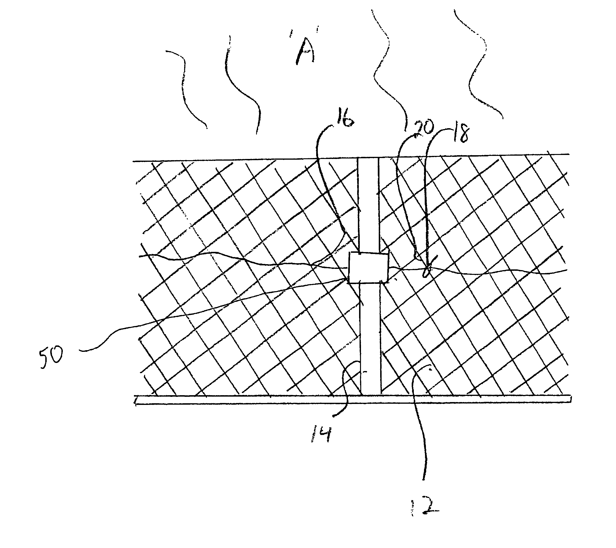
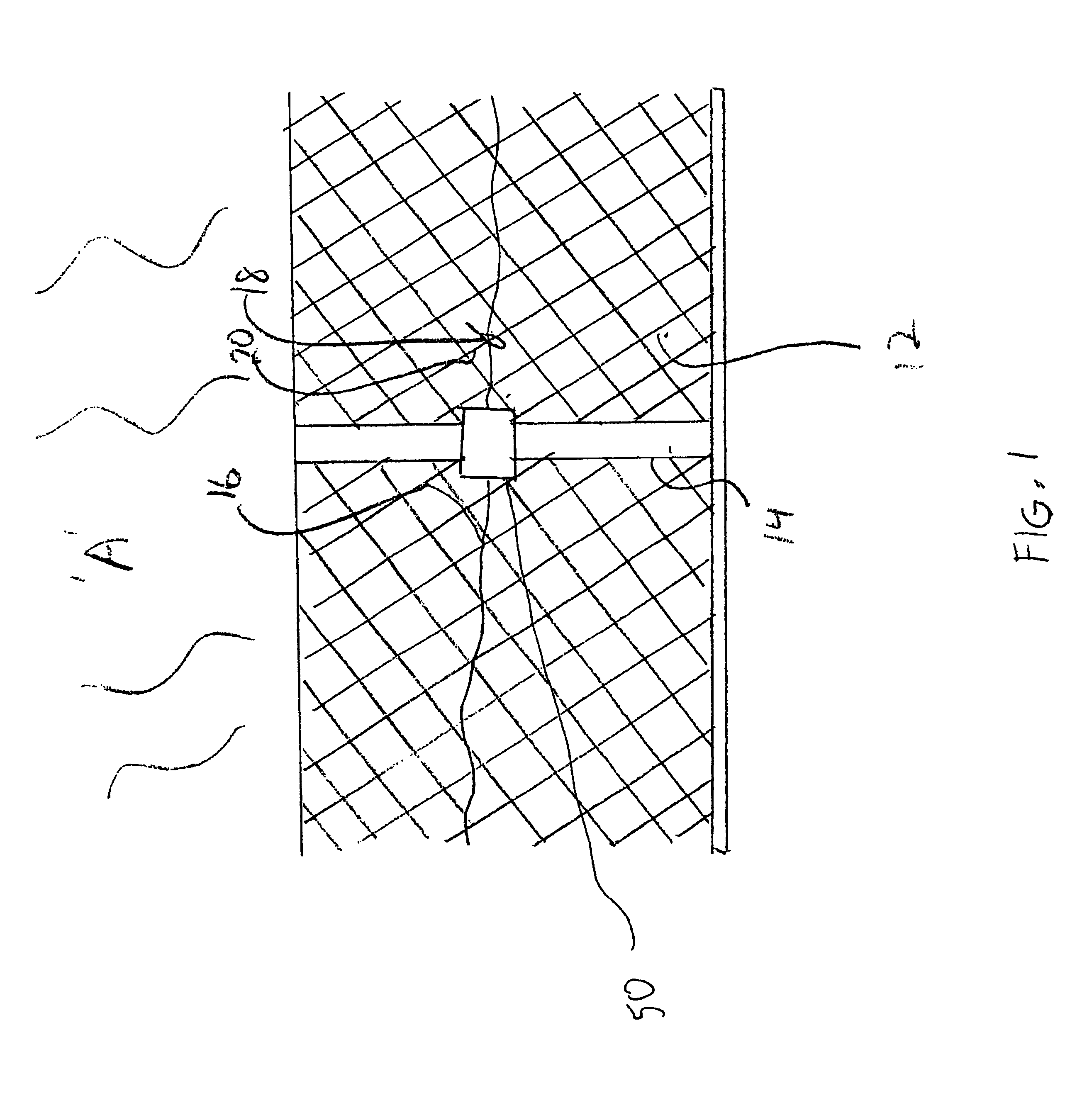
[0035]The invention will now be described in accordance with the Figs., in which FIG. 1 shows an area A bounded at certain perimeter locations by a fence 12. FIG. 1 shows the fence 12 as being a metallic chain link fence having multiple support posts 14. Other types of fences or boundary separators, such as wall structures etc. could also be equipped with the present invention to provide intrusion detection.

[0036]A fiber optic cable 16 is tightly secured to the fence 12 using any suitable fastening means. For our example, a tie-wrap 18 secures the fiber optic cable 16 to the fence links 20 at various locations. It is desirable to remove slack from the fiber optic cable 16 between the tie wraps 18.

[0037]Although FIG. 1 shows only one fiber optic cable 16 it will become apparent that a number of parallel or eccentrically spaced fiber optic cables would provide intrusion detection for different types of intrusion. For example, having one fiber optic cable 16 would be a cost effective s...


PUM


Abstract

There is provided an electronic security system for a perimeter structure that incorporates a fiber optic cable secured to the perimeter structure. Typically the perimeter structure is a fence. A light pulse is transmitted down the fiber optic cable. Mechanical attenuation devices disposed at various locations along the fiber optic cable are responsive to intrusion attempts. The mechanical attenuation devices produce measurable attenuations to the light pulse. Using backscattering light detection technology an intrusion attempt and the location of an intrusion is detected.

Description

FIELD OF THE INVENTION[0001]The present invention relates to the field of electronic intrusion detection systems, and more particularly, to an optical fiber cable based electronic intrusion detection system.BACKGROUND OF THE INVENTION[0002]There are many existing perimeter security systems that use optical fiber as the sensing medium. Initially these systems were based on using the fiber as a wave-guide for a light signal and then detecting the light on the opposite end of the fiber. A loss of light would trigger an alarm. For example, U.S. Pat. No. 4,399,430 to Kitchen describes sending light through a system of detachable connections concluding with a device to measure light loss. If any of those connections were to be broken, the end light detector would receive less light and thus trigger an X alarm.[0003]A more advanced optical fiber based intrusion detection system also implements optical fiber as the sensing medium, but instead of measuring for lost light it analyzes the back...

Claims


Application Information

Patent Timeline
27 Dec 2005
Publication
US6980108B1
IPC
G08B13/00; G08B13/12; G08B13/186
CPC
G08B13/124; G08B13/186
Inventors
GEBBIA, WOODS; BOROWIEC, RICHARD