

Communication apparatus with antenna
a technology of communication apparatus and antenna, which is applied in the direction of resonant antennas, substation equipment, transmission, etc., can solve the problems of inpractical form of antenna protruding from the ear pad part, the user may still shut out electric waves, and the great decrease in antenna gain
- Summary
- Abstract
- Description
- Claims
- Application Information
AI Technical Summary
Problems solved by technology
Method used
Image

Examples
first embodiment
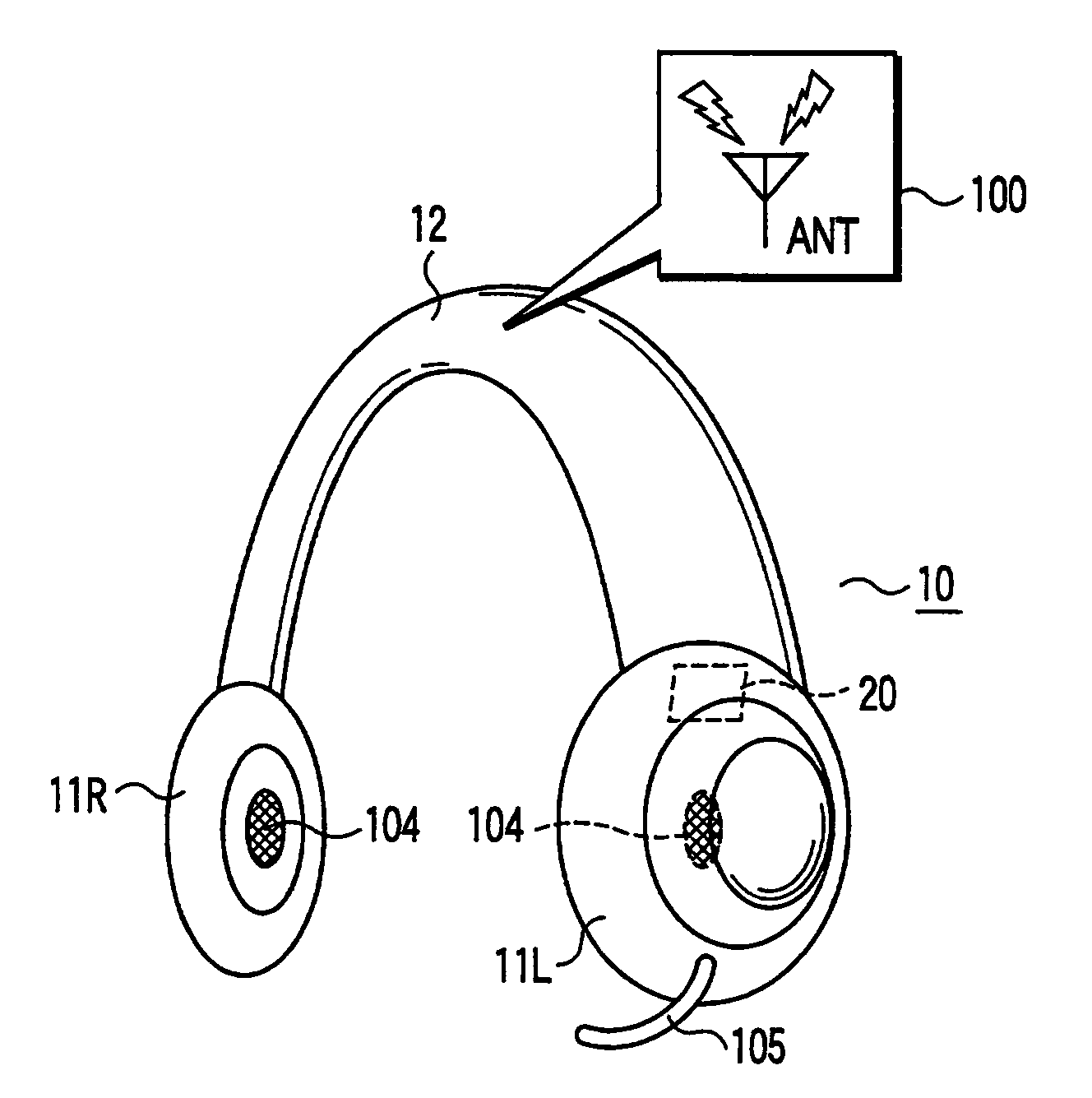
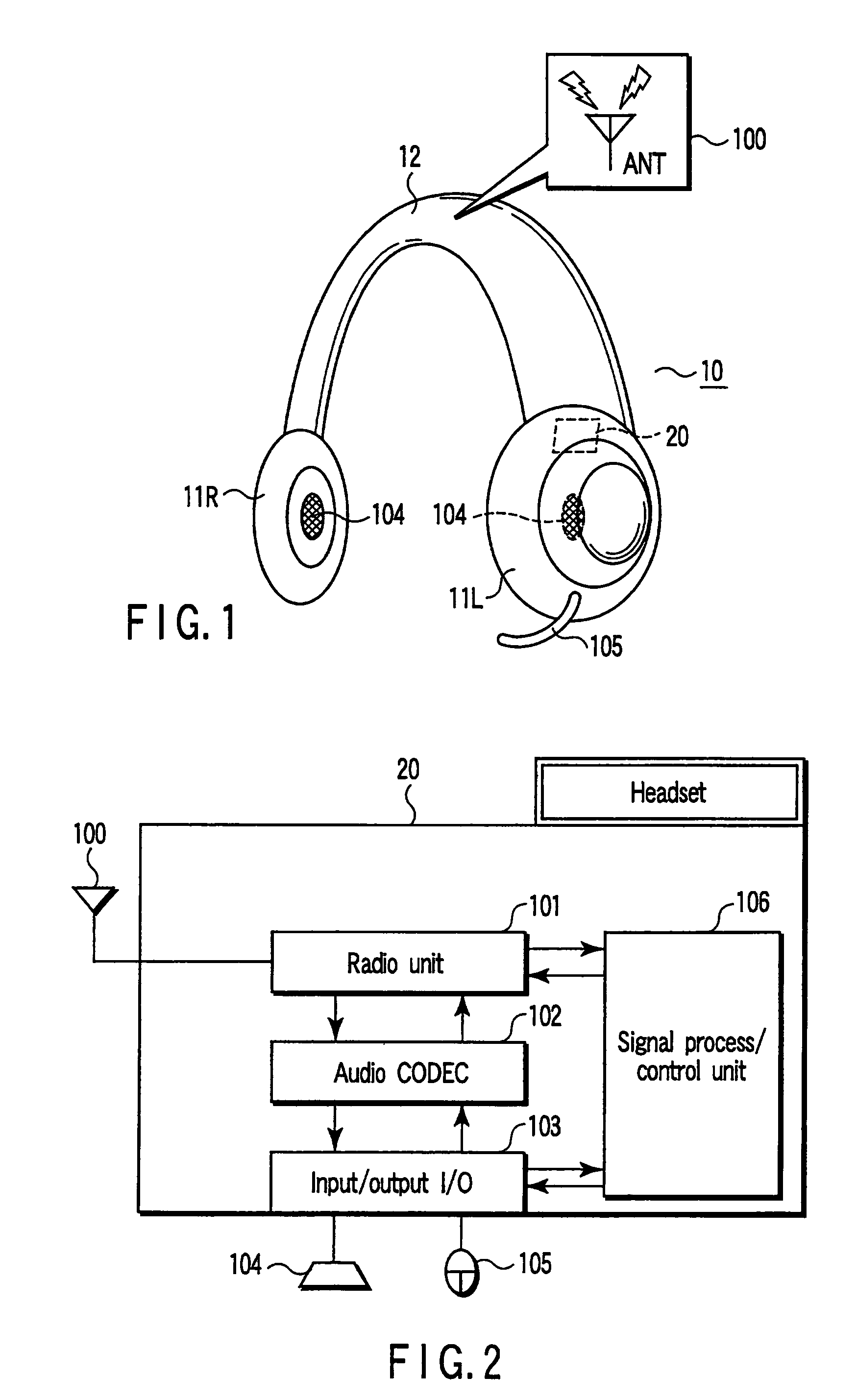
[0034]FIG. 1 shows a headset 10 as a communication apparatus according to a FIG. 2 shows a wireless communication module 20 arranged in the headset 10.
[0035]The headset 10 has left and right ear pads (earmuff parts) 11R and 11L, and a headband 12 corresponding to a coupling member which holds the ear pad 11R and 11L. Further, an antenna element 100 is included in the center part of the headband 12, i.e., the parietal region where a user wears the headset 10.
[0036]The headset 10 has a pair of speakers 104 for reproducing audio, and each of speakers 104 is arranged in each of the ear pads 11R and 11L respectively. In addition, the left ear pad 11L includes the wireless communication module 20 as shown in FIG. 2. A microphone 105 for inputting audio is shown mounted to protrude from the left ear pad 11L
[0037]As shown in FIG. 2, the wireless communication module 20 has a radio unit 101, an audio CODEC 102, an input / output interface 103, and a signal process / control unit 106. The radio ...
second embodiment
[0052]The structure of the second embodiment has advantages under certain types of situations such as when the headset 10 receives audio data from a digital audio player via wireless communication, and reproduces the sound through speakers 104 in the ear pad 11L and 11R or when the headset 10 establishes a wireless connection with a personal computer of the notebook type, or a cellular telephone, and various data is exchanged through the wireless connection.
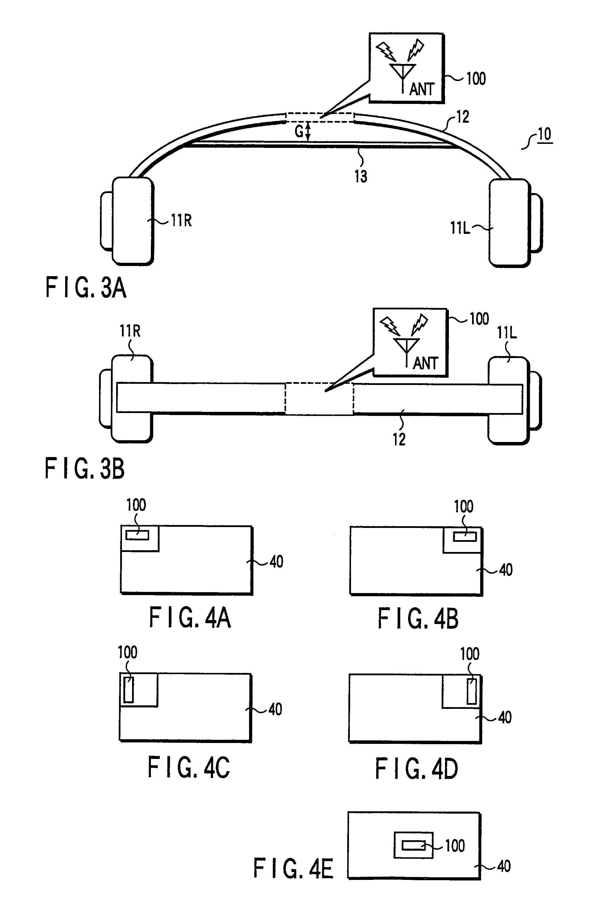
[0053]In these types of usage, the radiation characteristics in the front side of the user are particularly important when the user wears the headset 10 on the head. In addition, the headband 12 may be positioned forwards the rear, depending on the wearing conditions of the user and the shape of the user's head. The radiation characteristics may then deteriorate. Hence, if the FPC 40 is mounted on the headband 12, inclined at a certain inclination angle (θ°) to the forward direction, the radiation characteristics in the front sid...
third embodiment
[0055]Further, in the third embodiment, the ear pads 11R and 11L each include a speaker for reproducing audio. In addition, the left ear pad 11L includes a wireless communication module 30 or 50 as shown in FIG. 10 or 11. The wireless communication module 30 uses a power divider method in which electric power synthesis is performed on signals received by the respective antenna elements 100A and 100B. On the other hand, the wireless communication module 50 uses a diversity method in which power levels of signals received by the respective antenna elements 100A and 100B are compared and switched between the two.
[0056]Specifically, similar to the module 20 described as the first embodiment, the wireless communication module 30 of the power divider method has a radio unit 200, an audio CODEC 201, an input / output interface 202, and a signal process / control part 205. Further, the wireless communication module 30 has a power divider 206 connected to each of the antenna elements 100A and 10...
PUM
 Abstract
Description
Claims
Application Information