Process control instrument intrinsic safety barrier

Active Publication Date: 2005-12-27
AMETEK MAGNETROL USA LLC
View PDF3 Cites 19 Cited by
  • Summary
  • Abstract
  • Description
  • Claims
  • Application Information

AI Technical Summary

Benefits of technology

[0007]In accordance with the invention, there is disclosed a process control in

Problems solved by technology

Problems can arise if the medium in the tank is “hazardous”, i.e. it is subject to ignition and/or explosion.
Doing so may cause loss of loop power and supply voltage due to the protective compone

Method used


Image

  • Process control instrument intrinsic safety barrier
  • Process control instrument intrinsic safety barrier
  • Process control instrument intrinsic safety barrier

Examples


Embodiment Construction

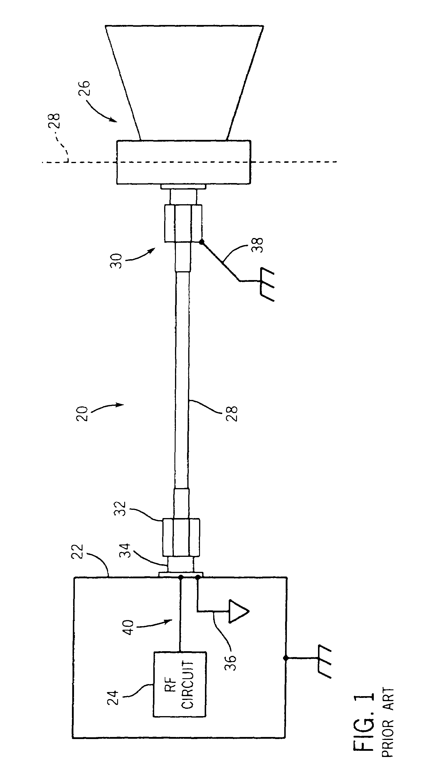
[0031]Referring initially to FIG. 1, a typical prior art through air radar process control instrument 20 comprises a conventional housing, represented by a block 22, housing various control circuits, including radio frequency (RF) circuits 24 for generating or receiving a high frequency microwave signal. An antenna 26 is mounted on a tank, represented by a dashed line 28, to direct electromagnetic energy toward a material in the tank. A typical circuit to couple a microwave signal between the RF circuit 24 and the antenna 26 uses a coaxial cable 28 having connectors 30 and 32. The first connector 30 is connected to the antenna 26. The second connector 32 is connected to a connector 34 operatively located in the housing 22. The coaxial cable 28 includes a center conductor and an outer shield, as is well known. The coaxial cable outer shield is usually connected to the circuit ground of the electronics, as illustrated at 36. The outer shield is also usually connected to earth ground, ...


PUM


Abstract

A process control instrument includes a circuit board having a control circuit for generating or receiving a high frequency signal. An antenna includes an electrical conductor. An intrinsic safety circuit couples the control circuit to the antenna and comprises a microstrip transmission line on the circuit board electrically connecting the control circuit to the electrical conductor. A safety stub has a first end electrically connected to the transmission line proximate the electrical conductor and a second end connected to a ground of the control circuit.

Description

CROSS REFERENCE[0001]This application claims priority of application No. 60 / 414,847 filed Sep. 30, 2002 and application No. 60 / 467,853 filed May 5, 2003.FIELD OF THE INVENTION[0002]This invention relates to a process control instrument and more particularly, to an intrinsic safety barrier for a process control instrument.BACKGROUND OF THE INVENTION[0003]Industrial processes often require measuring the level of liquid or other material in a tank. Many technologies are used for level measurement. With contact level measurement some part of the system, such as a probe, must contact the material being measured. With non-contact level measurement the level is measured without contacting the material to be measured. One example is non-contact ultrasound, which uses high-frequency audio waves to detect level. Another example is use of high-frequency or microwave RF energy. Microwave measurement for level generally uses either pulsed or frequency modulated continuous wave (FMCW) signals to ...

Claims


Application Information

Patent Timeline
IPC IPC(8): H01Q1/38H01Q23/00
CPCH01Q1/002H01Q1/38H01Q1/50H01Q23/00H01Q1/225
Inventor FLASZA, MICHAEL D.BLESZYNSKI, STANISLAW
Owner AMETEK MAGNETROL USA LLC
Why Eureka
Try Eureka