Inherently safe modular control system

a modular control system and modular technology, applied in process and machine control, process switching networks, instruments, etc., can solve problems such as fire risk, limited system power available, and insufficient operation of all field devices in the system

Active Publication Date: 2011-05-10
PHOENIX CONTACT GMBH & CO KG
View PDF8 Cites 28 Cited by
  • Summary
  • Abstract
  • Description
  • Claims
  • Application Information

AI Technical Summary

Benefits of technology

[0012]The invention embodies an improved interconnectivity approach to control systems that enables the control system to provide sufficient power to operate all field devices while still providing intrinsic safety for field devices in hazardous areas, without discrete safety barriers or specialized power supplies or connections.
[0017]The use of a backplane provides a number of advantages. Field modules can be easily added, without the need to add discrete safety barriers and without the need for additional engineering analysis. Field modules using different types of isolation circuits can be attached to the backplane for field devices located in different classes or divisions of hazardous areas. The trunk line can make full power available to modules connected to the backplane, and so additional modules can be added without intrinsic safety to deliver full power to field devices in safe areas. Additional types of devices can be connected to the backplane and interact with the control system.

Problems solved by technology

Field devices may be located in hazardous areas of the plant that present the risk of fire.
The problem with an intrinsically safe control system is that the limited power available in the system may be insufficient to operate all the field devices in the system, including those in safe areas.
The barrier provides a limited number of spurs that extend into the hazardous area, and limits the amount of current available to the spurs.
The limited current limits the number of field devices that can be attached downstream from the safety barrier.
For many industrial plants, providing and connecting a large number of separate and discrete safety barriers is expensive and takes up much valuable space.
FISCO solutions also require engineering analysis, and so tend to be expensive and complex.

Method used


Image

  • Inherently safe modular control system
  • Inherently safe modular control system
  • Inherently safe modular control system

Examples


Embodiment Construction

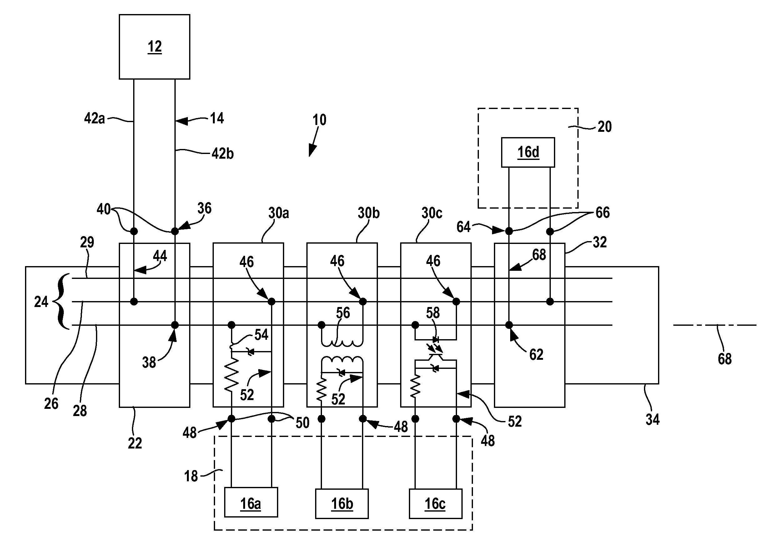
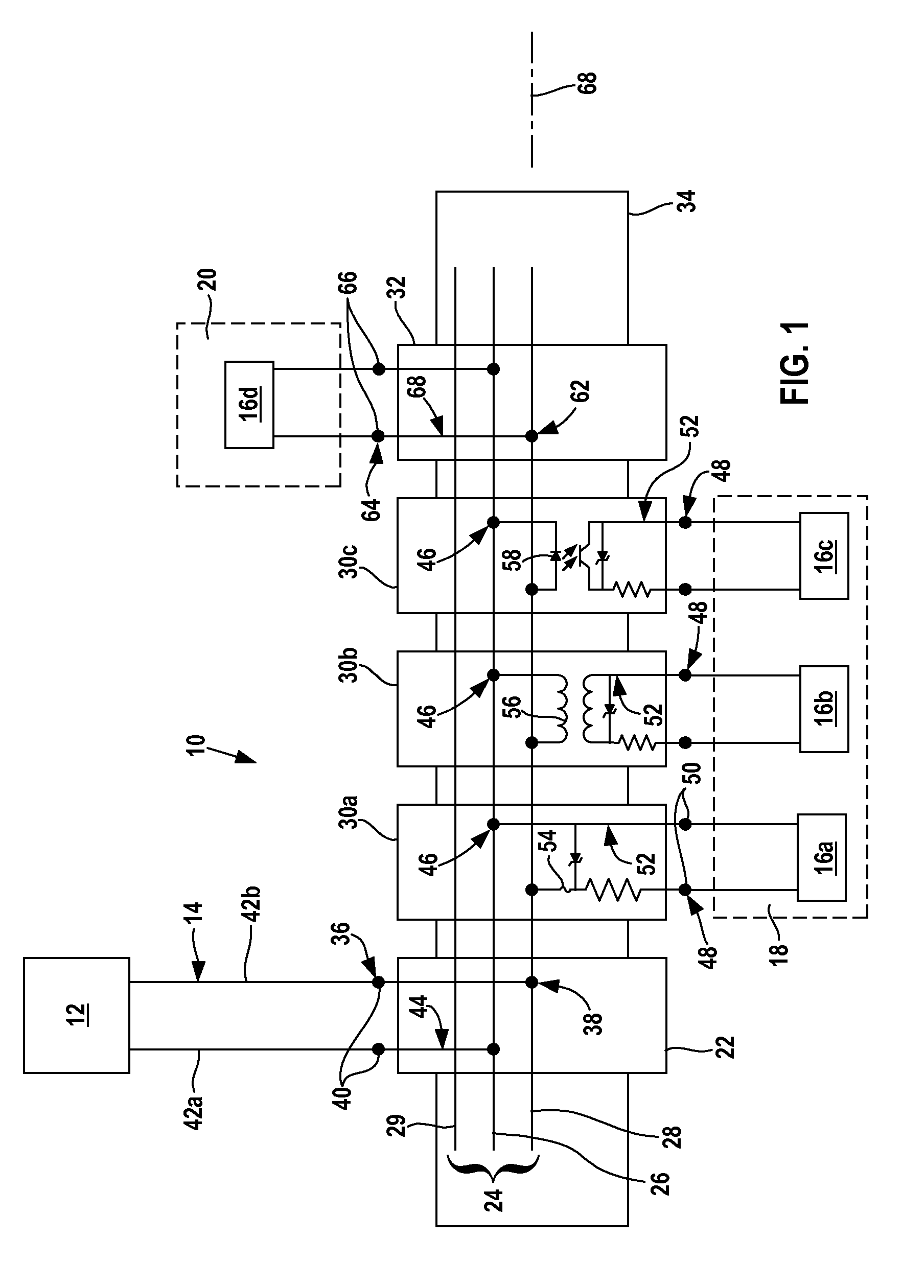
[0021]FIG. 1 illustrates a modular control system 10 for transmitting power and data between a control processor 12 that receives and transmits signals along trunk 14 and field devices 16a, 16b, 16c, and 16d. Each field device 16a-c is located in a hazardous area 18. Field device 16d is located in a safe area 20. The illustrated control system 10 is a fieldbus system.

[0022]Although the trunk 14 is shown extending directly from the control processor 12 to the control system 10, there may be other device couplers (not shown) or other control systems similar to control system 10 located downstream from the control system 10 or located along the trunk 14 between the control processor 12 and the control system 10. Other network topologies may also be used.

[0023]The control system 10 is connected between the trunk 14 and the field devices 16 and transmits power from the trunk 14 to the field devices 16 and transmits data signals between the trunk 14 and the field devices 16. The field dev...


PUM


Abstract

A modular system for transmitting power and data between a control processor that receives and transmits signals along a trunk of a distributed control network, and one or more field devices located in a hazardous area includes a backplane bus and a trunk module connected to the backplane and interconnecting the trunk and backplane. Intrinsically safe spur modules are removably attached to the backplane.

Description

FIELD OF THE INVENTION[0001]The invention relates to a control system for real-time distributed control, and more specifically, to a control system that provides an inherently safe interface between a main trunk and field devices of the control system.BACKGROUND OF THE INVENTION[0002]Automated industrial systems have field devices that monitor, control, and operate an industrial process. The field devices communicate with a control processor through a trunk that transmits power to the field devices and transmits data signals (which can include operating commands) between the control processor and the field devices. The field devices each attach to the trunk via a spur or branch connection. The field devices can be distributed throughout the industrial plant, and the data transmittal rates allow essentially real-time control of the process.[0003]Standardized power and communication protocols have been developed for distributed control systems. For example, the Foundation Fieldbus pro...

Claims


Application Information

Patent Timeline
Patent Type & Authority Patents(United States)
IPC IPC(8): H02H3/00
CPCH04L12/40045H04L2012/40221
Inventor HELFRICK, BRENTON EUGENEKREIDER, AARON RICHARDVOGT, BRIAN JAMESMATHEWS, DAVIS
Owner PHOENIX CONTACT GMBH & CO KG
Why Eureka
Try Eureka