Three-dimensional image display apparatus and color reproducing method for three-dimensional image display

a three-dimensional image and display apparatus technology, applied in the direction of instruments, static indicating devices, lenses, etc., can solve the problems of failure in correct color reproduction, great obstacle, and inability to reprodu

Inactive Publication Date: 2005-12-27
CANON KK
View PDF8 Cites 96 Cited by
  • Summary
  • Abstract
  • Description
  • Claims
  • Application Information

AI Technical Summary

Benefits of technology

[0020]Thus, at a viewing position of said three-dimensional image display apparatus at an optimal viewing distance, color reproduction is carried out while maintaining the ratio of brightness of the three RGB primary colors at a predetermined value in each of the respective parallax images.

Problems solved by technology

However, pixels of a color display device which is capable of full-color display usually consist of red sub-pixels, green sub-pixels, and blue sub-pixels, therefore, if the color display device is viewed through minute apertures or lights from minute light sources are viewed through a transmission type color display device, color eclipses where only a part of a parallax image pixel composed of three red, green, and blue sub-pixels appears lighted and crosstalk occur in parallax images wherein correct color reproduction cannot be carried out.
Failure in correct color reproduction due to color eclipses and crosstalk becomes a great obstacle to achievement of a high sense of reality required for a three-dimensional image display apparatus.
However, in such a method, since a color display device having RGB vertically-striped sub-pixels, which has been popularized to construct a three-dimensional image display apparatus having a landscape screen, cannot be used, initial costs for commercialization become prohibitive.
In addition, in a three-dimensional display apparatus using a minute light source array and a transmission type liquid crystal display, even if diffraction at a black matrix is reduced by providing RGB horizontal stripes, it is difficult to suppress scattering based on optical nonuniformity in identical sub-pixels.

Method used


Image

  • Three-dimensional image display apparatus and color reproducing method for three-dimensional image display
  • Three-dimensional image display apparatus and color reproducing method for three-dimensional image display
  • Three-dimensional image display apparatus and color reproducing method for three-dimensional image display

Examples


numerical example 1

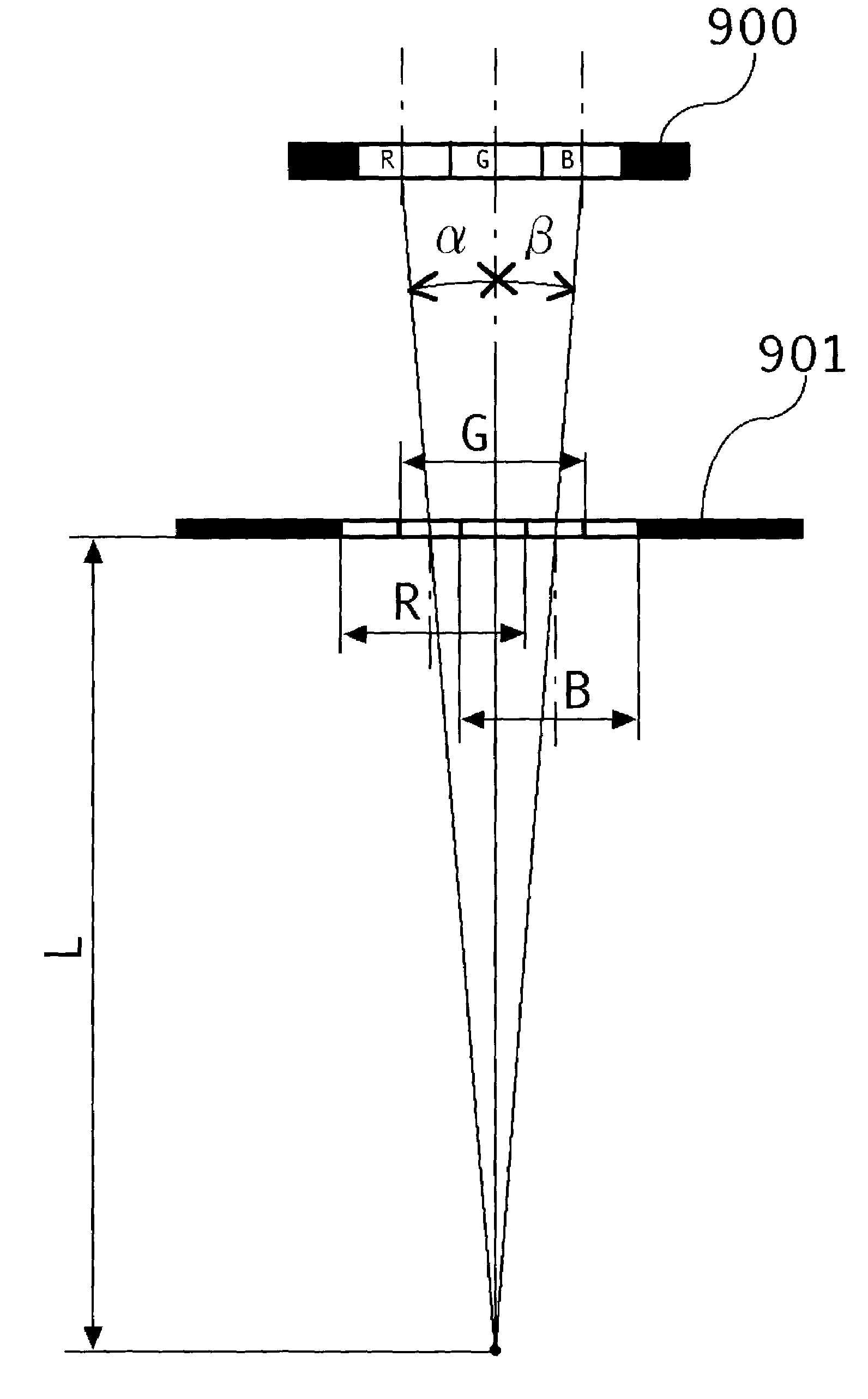
[0099]FIG. 12(a) is a detailed explanatory diagram of the three-dimensional image display apparatus shown in FIG. 1.

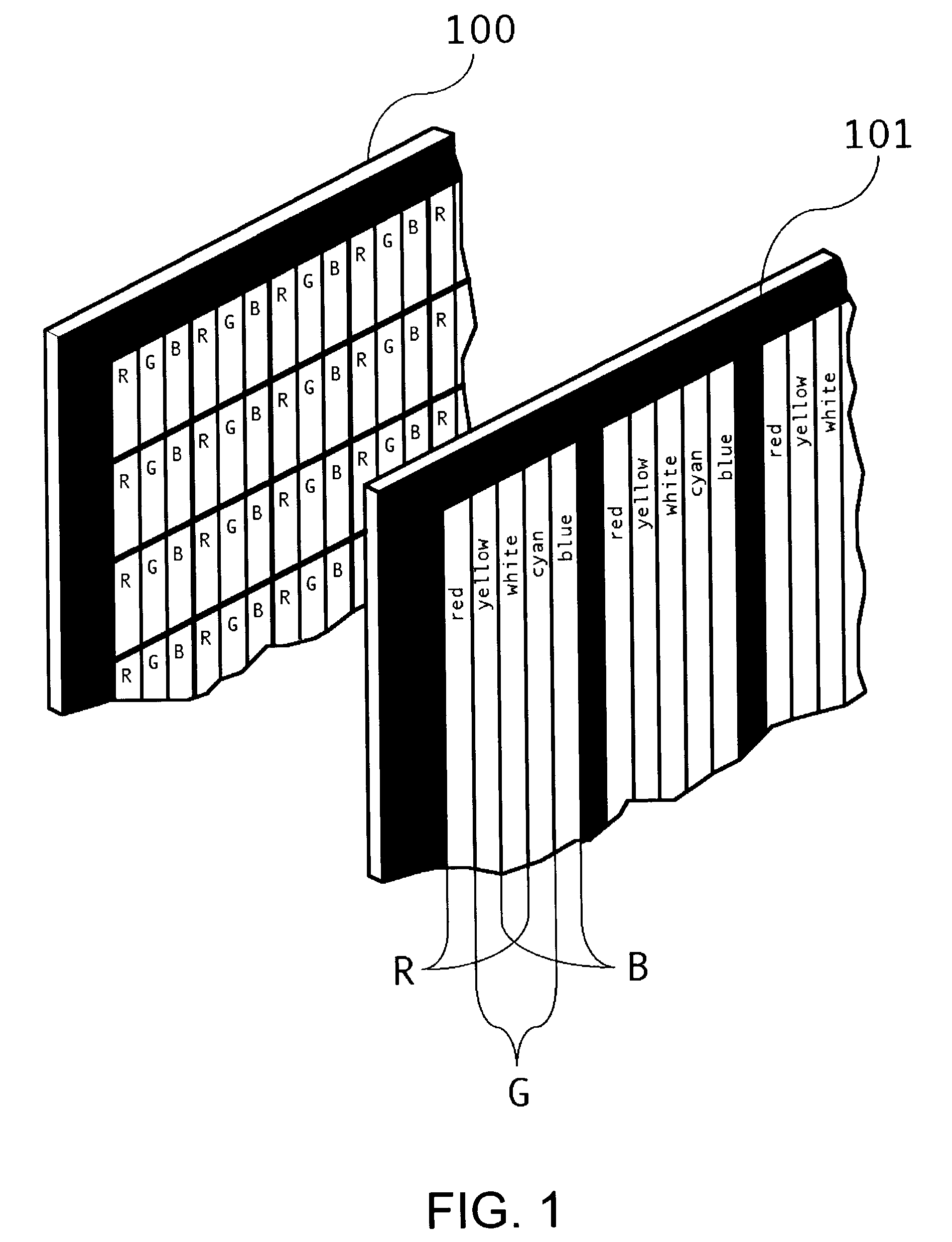
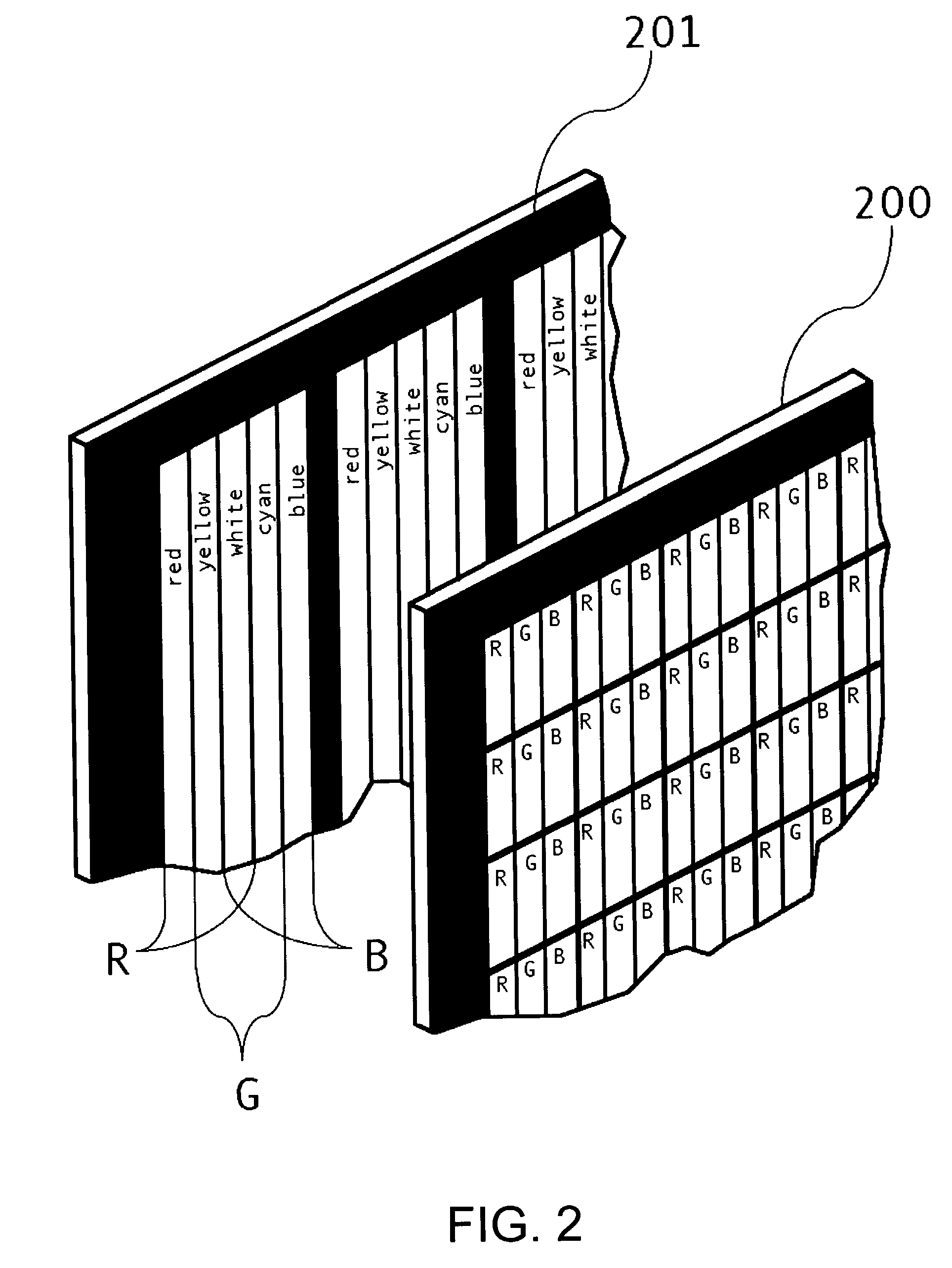
[0100]A display device 11 is composed of vertically-striped RGB sub-pixels (a pixel unit as a unit of display), and as such a display device, a liquid crystal display, a plasma display, etc., can be mentioned. A shading mask 12 with a minute aperture array is provided on the display surface side (in front of) of the display device 11.

[0101]FIG. 12(b) is an explanatory diagram of the shading mask 12 with a minute aperture array.

[0102]The shading mask 12 with a minute aperture array is composed of shading parts shown by black paint and minute aperture parts having five types of vertically-striped color filters of red, yellow, white (or transparent), cyan, and blue. The shading parts and the minute aperture parts are alternatively provided in the horizontal direction.

[0103]An image controller 13 is connected to the display device 11, and by the image controller 13, displa...

numerical example 2

[0156]FIG. 17 is a detailed explanatory diagram of a three-dimensional image display apparatus of FIG. 2.

[0157]A transmission type display device 14 is composed of vertically-striped RGB sub-pixels, and as such a display device, a liquid crystal display, etc., can be mentioned.

[0158]On the rear surface side (the side opposite to the viewing surface) of the transmission type display device 14, a minute light source array 15 is provided.

[0159]The minute light source array 15 is composed of shading parts (non-light-emitting parts) shown by black painting and light source parts (light-emitting parts) five types of vertically-striped light source of red, yellow, white, cyan, and blue. The shading parts and the light source parts are alternatively provided in the horizontal direction.

[0160]It is also possible to construct such a light source array by use of a white backlight and a color filter mask with a pattern of a shading part and color filter part of vertically-striped red, yellow, w...

numerical example 3

[0190]FIG. 20 is a detailed explanatory diagram of a three-dimensional image display apparatus of the embodiment shown in FIG. 3.

[0191]As mentioned above, a vertical cylindrical lens array 18 is provided to improve utilization efficiency of light of a minute light source array 19. In addition, by a shading mask 17 with a minute aperture array, scattered light which occurs in a transmission type display device 16 is cut, therefore, crosstalk is low.

[0192]The transmission type display device 16 is composed of vertically-striped RGB sub-pixels. An image controller 13 is connected to the transmission type display device 16 and display of a composite parallax image is controlled by the image controller 13. The composite parallax image is identical to that described in terms of FIG. 12c.

[0193]On the display surface side of the transmission type display device 16, the shading mask 17 with a minute aperture array is provided, and on the rear surface (the side opposite to the display surfac...


PUM


Abstract

In a three-dimensional image display apparatus provided with a shading mask with a minute aperture array in front of a color display device, the minute apertures are provided with color filters, a setting is provided so that the visual angles between the respective centers of the red-light transmitting part, green-light transmitting part, and blue-light transmitting part of the color filters become equal, in an identical parallax image pixel region, to the visual angles between the respective centers of the red, green, and blue sub-pixels of the color display device, the respective red, green, and blue sub-pixels are made so as to be always displayed in a lighted condition at a fixed area ratio, thus color reproduction wherein brightness ratio of the three primary colors in respective parallax image pixels is maintained at an appointed value is carried out.

Description

BACKGROUND OF THE INVENTION[0001]1. Field of the Invention[0002]The present invention relates to a three-dimensional image display apparatus using a minute aperture array and a minute light source array and a color reproducing method in a three-dimensional image display apparatus.[0003]2. Description of the Related Art[0004]Since three-dimensional image display apparatuses using a minute aperture array and a minute light source array have an advantage such that naked-eye stereoscopic vision can be realized with a simple structure, these have been put to practical use as parallax barrier—or linear light source array-type three-dimensional image display apparatuses.[0005]However, pixels of a color display device which is capable of full-color display usually consist of red sub-pixels, green sub-pixels, and blue sub-pixels, therefore, if the color display device is viewed through minute apertures or lights from minute light sources are viewed through a transmission type color display d...

Claims


Application Information

Patent Timeline
Patent Type & Authority Patents(United States)
IPC IPC(8): G02B30/27G02B3/00H04N13/00H04N15/00
CPCG02B27/2214H04N13/0404H04N13/0406H04N13/0409H04N13/0422H04N13/0445H04N13/0477H04N13/0497H04N13/305H04N13/32H04N13/376H04N13/324H04N13/31H04N13/349H04N13/307H04N13/398G02B30/27
Inventor MATSUMOTO, KAZUMINISHIHARA, HIROSHI
Owner CANON KK
Why Eureka
Try Eureka