
Enhanced coplanar conductance structure for inductive heads

Inactive Publication Date: 2005-12-27
IBM CORP
View PDF7 Cites 4 Cited by
  • Summary
  • Abstract
  • Description
  • Claims
  • Application Information

AI Technical Summary

Benefits of technology

[0012]To overcome the limitations in the prior art described above, and to overcome other limitations that will become apparent upon reading and understanding the present specifica

Problems solved by technology

Fabricating high aspect ratio copper coils, as used in the magnetic inductive write head, is becoming increasingly more difficult to create using tradition electroplating on top of a copper containing a seed layer.
Further, it is difficult to use electroplating to produce a conformal seed layer that minimizes discontinuities.
These seed layers are not always continuous or plating tends to produce voids in high aspect ration structures.
However, removal of the seed has become difficult with sub-micron spacing between the coils.

Method used


Image

  • Enhanced coplanar conductance structure for inductive heads
  • Enhanced coplanar conductance structure for inductive heads
  • Enhanced coplanar conductance structure for inductive heads

Examples


Embodiment Construction

[0038]In the following description of the exemplary embodiment, reference is made to the accompanying drawings, which form a part hereof, and in which is shown by way of illustration the specific embodiment in which the invention may be practiced. It is to be understood that other embodiments may be utilized as structural changes may be made without departing from the scope of the present invention. Although the drawings are intended to illustrate the present invention, the drawings are not necessarily drawn to scale.

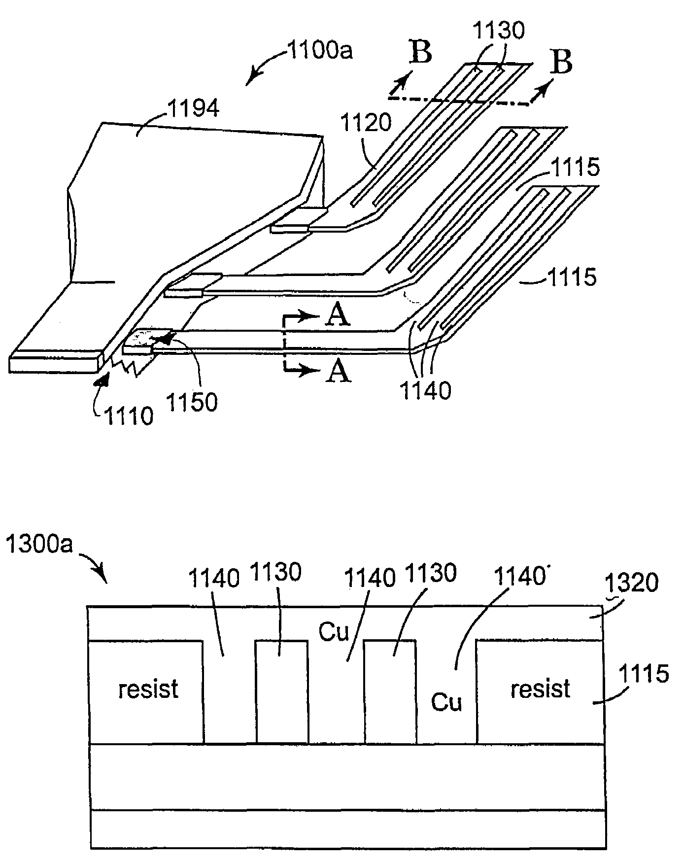
[0039]The present invention forms a high conductance, high aspect ratio structure in a single low temperature copper chemical vapor deposition step. The present invention uses a low temperature, conformal coverage copper chemical vapor deposition technique that includes topographical features to increase a conformal coverage area. Multiple coil trenches are created in nonconfined areas of a coil structure and these multiple coil trenches also create a lower resistance i...


PUM

PropertyMeasurementUnit
Temperatureaaaaaaaaaa
Electrical resistanceaaaaaaaaaa
Electrical conductanceaaaaaaaaaa

Abstract

A high aspect ratio structure using topographical features to increase conformal coverage area provides high conductance. An insulation layer is disposed over a magnetic material. At least one trench is formed in the insulation layer to form a coil, where the at least one trench forms the coil with multiple coil windings. A plurality of topographical features is formed in at least one nonconfined area of the coil to increase conformal coverage area. A metal, such as copper, is deposited into the at least one trench and topographical features to form an inductive structure.

Description

BACKGROUND OF THE INVENTION[0001]1. Field of the Invention[0002]This invention relates in general to magnetic transducers, and more particularly to a method and apparatus for forming a high conductance, high aspect ratio structure in a single low temperature copper chemical vapor deposition step.[0003]2. Description of Related Art[0004]Magnetic recording is a key and invaluable segment of the information-processing industry. While the basic principles are one hundred years old for early tape devices, and over forty years old for magnetic hard disk drives, an influx of technical innovations continues to extend the storage capacity and performance of magnetic recording products. For hard disk drives, the areal density or density of written data bits on the magnetic medium has increased by a factor of more than two million since the first disk drive was applied to data storage. Since 1991, areal density has grown by the well-known 60% compound growth rate, and this is based on correspo...

Claims


Application Information

Patent Timeline
IPC IPC(8): G11B5/17
CPCG11B5/17Y10T29/49064Y10T29/4906Y10T29/49073
Inventor LILLE, JEFFREY S.
Owner IBM CORP
Learn More