
Data center cooling system

a data center and cooling system technology, applied in the direction of domestic cooling apparatus, lighting and heating apparatus, and semiconductor/solid-state device details, etc., can solve problems such as power supply interruption

Inactive Publication Date: 2005-12-27
SCHNEIDER ELECTRIC IT CORP
View PDF7 Cites 201 Cited by
  • Summary
  • Abstract
  • Description
  • Claims
  • Application Information

AI Technical Summary

Benefits of technology

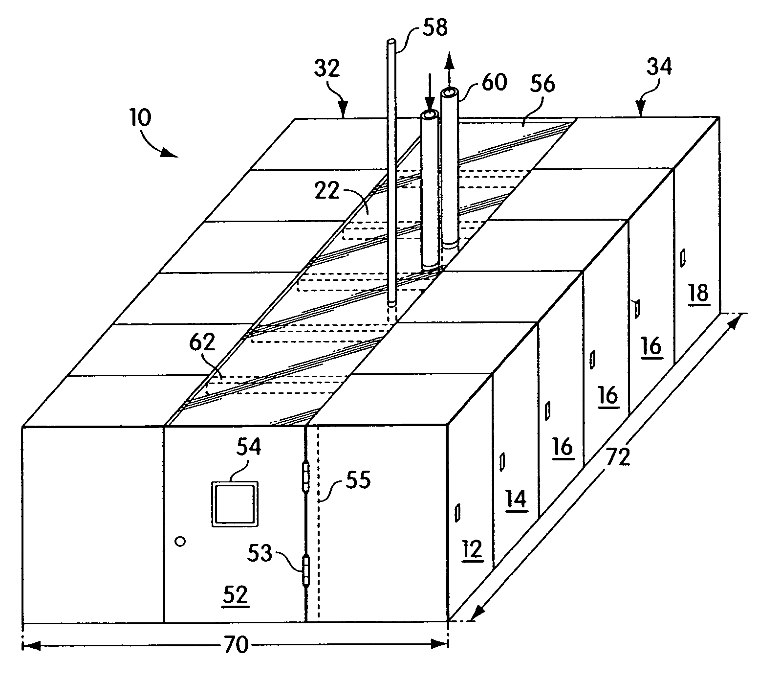
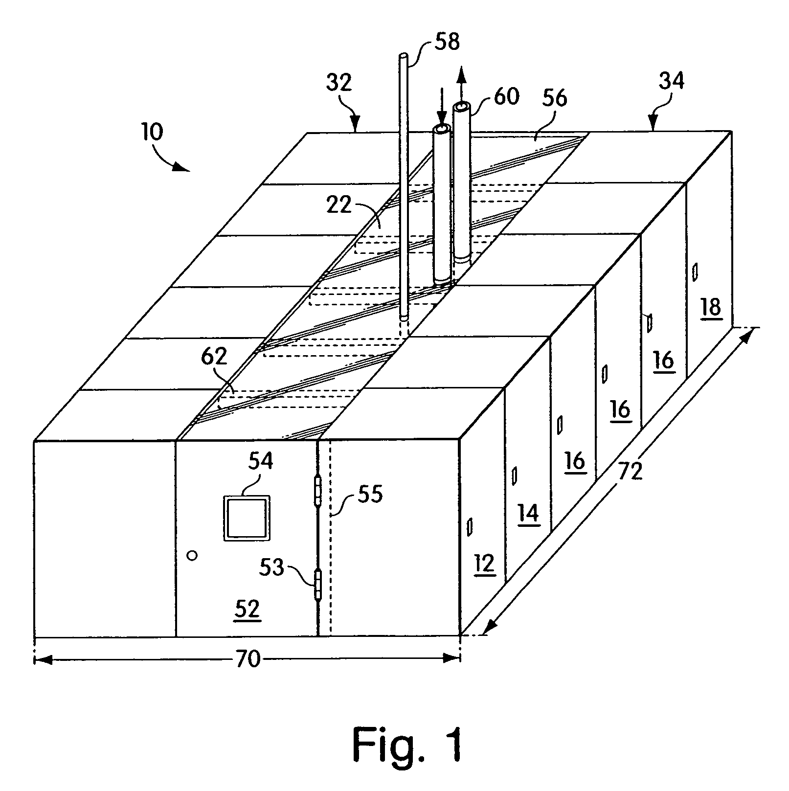
[0037]Other embodiments are within the scope and spirit of the appended claims. For example, air could be forced up through the equipment racks 18. Air moved through the racks 18 could be of varying temperatures, including hot air. The data center 10 may be configured to distribute gases other than air. Additionally, a refrigerant or other coolant may be used rather than cold water. Further, a controller can be coupled to the data center 10 to monitor air temperatures and flow rates, as well as power supply so that each rack is provided adequate power consistently. A data center may contain a single equipment rack 18 having a single cooling unit 16 creating an individual data center, whereby power is distributed to a single data center 10 or multiple single-rack data centers simultaneously.

Problems solved by technology

Additionally, the method can include using an uninterruptible power supply to provide power to equipment in the racks.

Method used


Image

  • Data center cooling system
  • Data center cooling system
  • Data center cooling system

Examples


Embodiment Construction

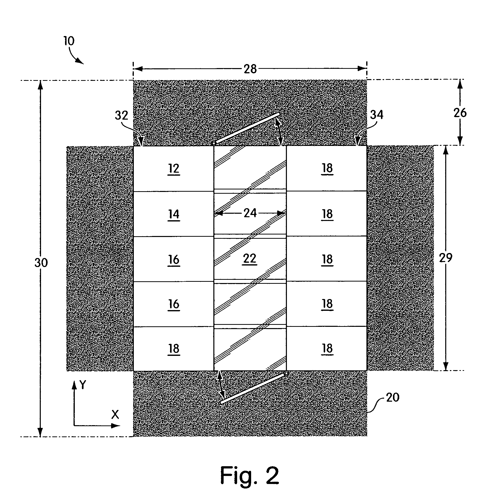
[0016]Embodiments of the invention provide a data center infrastructure having a cooling system for cooling rack-mounted electronic equipment. Embodiments of the invention provide a modular data center for rack-mounted equipment, wherein the modular data center provides power distribution, cooling and structural support for the rack-mounted equipment. The power distribution unit and cooling is provided in some embodiments using redundant systems to prevent downtime due to electrical or mechanical failures. As understood by those skilled in the art, other embodiments are within the scope of the invention, such as embodiments used to provide infrastructure for equipment other than electronic equipment.

[0017]A system for providing power distribution for rack-mounted equipment which can be used with embodiments of the present invention is described in U.S. patent application Ser. No. 10 / 038,106, entitled, “Adjustable Scalable Rack Power System and Method,” which is herein incorporated b...


PUM


Abstract

A modular data center includes a plurality of racks, each of the racks having a front face and a back face, wherein the plurality of racks is arranged in a first row and a second row, such that the back faces of racks of the first row are facing the second row, and the back faces of the racks of the second row are facing the first row, a first end panel coupled between a first rack of the first row and a first rack of the second row, the first end panel having a bottom edge and a tope edge, a second end panel coupled between a second rack of the first row and a second rack of the second row, the second end panel having a top edge and a bottom edge, and a roof panel coupled between the top edge of the first panel and the top edge of the second panel.

Description

CROSS-REFERENCE TO RELATED APPLICATIONS[0001]This application is a continuation application under 37 CFR §1.53(b) of U.S. Ser. No. 10 / 391,971, (U.S. Pat. No. 6,859,366), filed on Mar. 19, 2003, and entitled, “Data Center Cooling System,” which is assigned to the assignee of this application and is herein incorporated by reference in its entirety.FIELD OF THE INVENTION[0002]Embodiments of the present invention are directed to cooling of rack-mounted devices, and more particularly to a data center infrastructure having a cooling system.BACKGROUND OF THE INVENTION[0003]Electronic equipment racks generally are designed to receive a number of electronic components arranged vertically in the rack, mounted on shelves, and / or to front and rear mounting rails. The electronic equipment may include, for example, printed circuit boards, communications equipment, computers, including computer servers, or other electronic components.[0004]Electronic equipment housed in racks produces a considerab...

Claims


Application Information

Patent Timeline
Patent Type & Authority Patents(United States)
IPC IPC(8): H05K7/20
CPCE04H5/02E04H2005/005H05K7/20745H05K7/2079
Inventor FINK, JAMES
Owner SCHNEIDER ELECTRIC IT CORP
Learn More