Circuit for starting power source apparatus

a power source and circuit technology, applied in the direction of electric variable regulation, process and machine control, instruments, etc., can solve the problems of insufficient input voltage of dc/dc conversion circuit b>20/b>, affecting the operation of one control unit, and reducing the efficiency of the starting circui

Inactive Publication Date: 2005-12-27
SANKEN ELECTRIC CO LTD
View PDF7 Cites 83 Cited by
  • Summary
  • Abstract
  • Description
  • Claims
  • Application Information

AI Technical Summary

Problems solved by technology

However, there are problems such as below, in the starting method and starting circuit of the conventional switching power source.
This hinders miniaturization and low cost of starting circuits, and switching power source apparatuses that have them built in.
Further, another significant problem is that by the variation in starting voltage of the control units 19 and 29, starting deficiency in that the operation of one control unit starts, but the other does not, and the output voltage of the power factor improvement circuit 10 or the DC / DC conversion circuit 20 dropping by the power being taken up by the control unit that starts first, occurring by the starting time of the control units not matching.
As a result, the input voltage of the DC / DC conversion circuit 20 is not sufficient, and adequate energy can not be supplied to the output side.

Method used


Image

  • Circuit for starting power source apparatus
  • Circuit for starting power source apparatus
  • Circuit for starting power source apparatus

Examples


Embodiment Construction

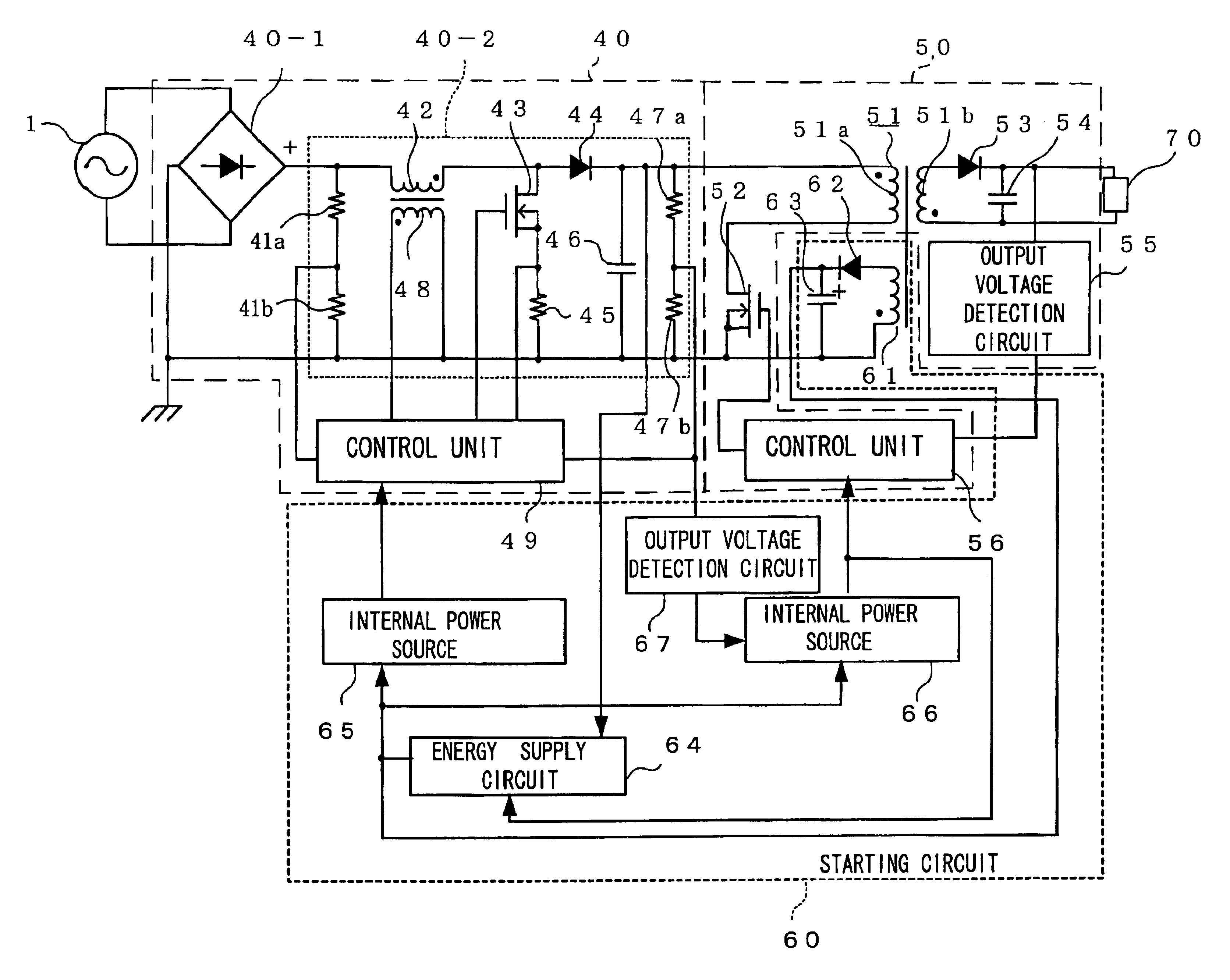
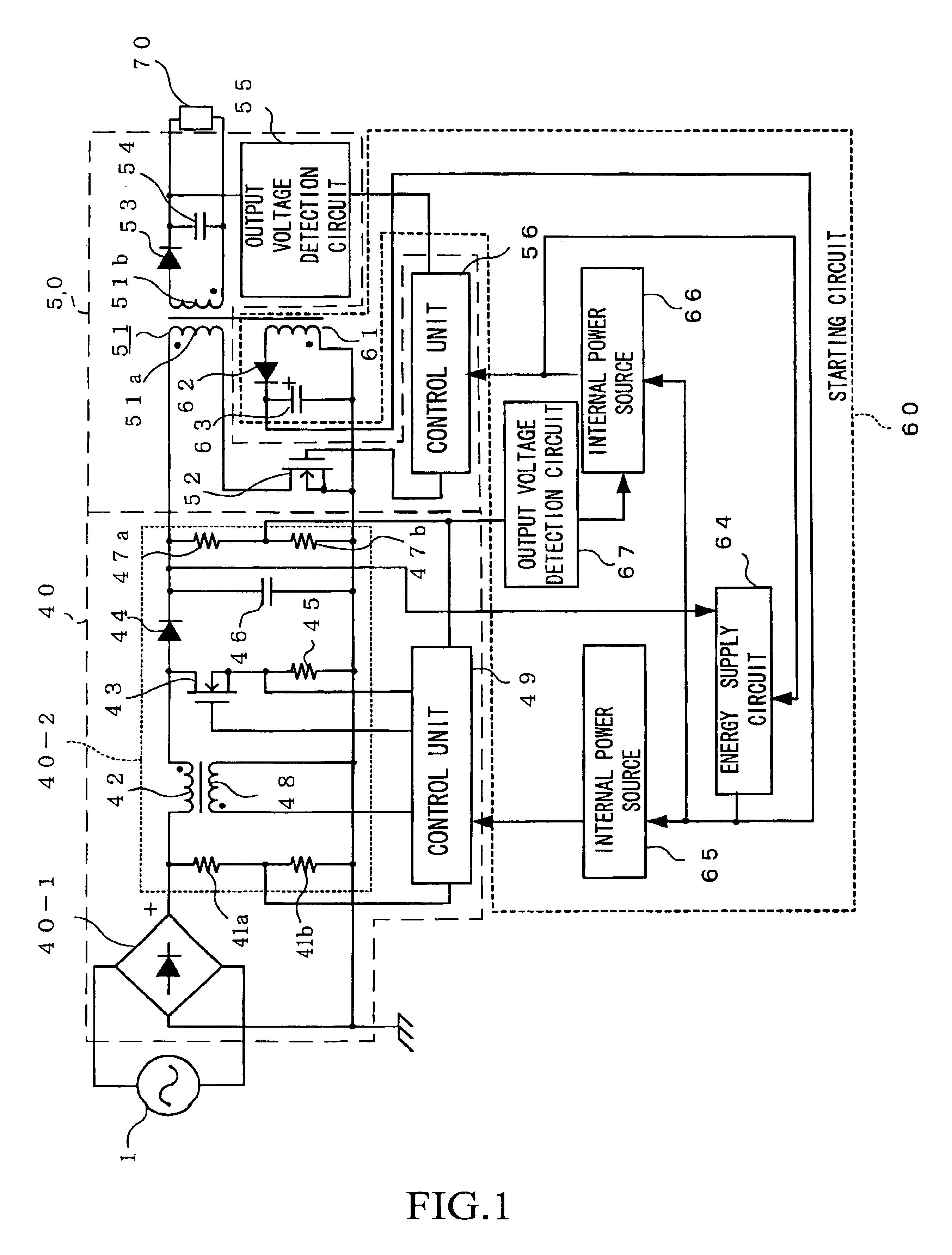
[0100]FIG. 1 is a structural diagram showing a starting circuit and a switching power source apparatus according to an embodiment of the present invention.

[0101]The switching power source apparatus comprises an AC / DC conversion circuit 40 that is connected to an AC power source 1, a DC / DC conversion circuit 50 that is connected to the AC / DC conversion circuit 40, and a starting circuit 60 that starts the operation of the AC / DC conversion circuit 40 and the DC / DC conversion circuit 50. The AC / DC conversion circuit 40 comprises a rectifier circuit 40-1 that is connected to the AC power source 1, and a power factor improvement circuit 40-2. A first control unit 49 that controls switching operation of the power factor improvement circuit 40-2 is provided in the power factor improvement circuit 40-2, and a second control unit 56 that controls switching operation of the DC / DC conversion circuit 50 is provided in the DC / DC conversion circuit 50.

[0102]The starting circuit 60 of the switchin...


PUM


Abstract

When an AC power source (1) is turned on, energy is accumulated in a backup capacitor (63) by an energy supply circuit (64). An internal power source (65) supplies the energy accumulated in the capacitor (63) to a control unit (49). Thus, a power factor improvement circuit (40-2) operates. When the power factor improvement circuit (40-2) operates to output a predetermined voltage, an output voltage detection circuit (67) detects the voltage, and switches the internal power source (66) on. The turned on internal power source (66) supplies the energy in the capacitor (63) to a control unit (56) to operate a DC / DC conversion circuit (50). In this way, by operating the DC / DC conversion circuit (50) after operating the power factor improvement circuit (40-2), the capacity of the capacitor (63) can be reduced.

Description

TECHNICAL FIELD[0001]The present invention relates to a power source apparatus starting method, a starting circuit of a power source apparatus, and a power source apparatus.BACKGROUND ART[0002]To deal with the Harmonic Current Regulation (IEC610003-2) and the Appliance / commodity harmonic current suppressing guideline, a switching power source apparatus that has a power factor improving function is included in an AC adapter, an office automation equipment, or various commercial-devices. Concerning these AC adapters, office automation equipments, and various commercial-devices, also, miniaturization, lower costs, and saving of energy is desired. These kinds of switching power source apparatuses are disclosed in for example the below documents.[0003]Document 1: Examined Japanese Patent Application KOKOKU Publication No. H7-57095[0004]Document 2: Unexamined Japanese Patent Application KOKAI Publication No. H6-121535[0005]In Examined Japanese Patent Application KOKOKU Publication No. H7-...

Claims


Application Information

Patent Timeline
Patent Type & Authority Patents(United States)
IPC IPC(8): H02M1/00H02M1/36H02M1/42
CPCH02M1/36H02M1/4208Y02B70/126Y02B70/10H02M3/28
Inventor SIMADA, MASAAKIYAMADA, TOMOYASU
Owner SANKEN ELECTRIC CO LTD
Why Eureka
Try Eureka