Radio system

a radio system and receiver technology, applied in the field of radio systems, can solve the problems of inability to offer high-quality services, substation equipment, and substations to face each other, and achieve the effects of preventing interference, saving frequency resources, and preventing the occurrence of interferen

Inactive Publication Date: 2005-12-27
KOKUSA ELECTRIC CO LTD
View PDF9 Cites 8 Cited by
  • Summary
  • Abstract
  • Description
  • Claims
  • Application Information

AI Technical Summary

Benefits of technology

[0035]According to still another aspect of the present invention, there is provided a radio communication system that divides a certain region into two or more cells and installs a base station in each cell to carry out communication between the base station and many fixed terminal stations in the cell in which the base station is installed, wherein the base station is installed near the edge of the cell, all the antennas at the base station are made possible communication throughout the same range of the horizontal direction and placed to face in the same direction, and adjacent cells use different frequencies or different polarized wave for radio communication. This configuration not only prevents the occurrence of interference between base stations, but also save the utilization of frequency resources.
[0036]According to yet another aspect of the present invention, there is provided a radio system that divides a certain region into two or more cells and installs a base station in each cell to carry out communication between the base station and many fixed terminal stations in the cell in which the base station is installed, wherein the base station is installed near the edge of the cell, each cell is divided into two or more sectors, each of which is provided with an antenna, all the antennas at the base station are made possible communication throughout the same range of the horizontal direction, and placed not to face the other base stations, and adjacent cells use different frequencies or different polarized waves for radio communication. This configuration not only prevents the occurrence of interference between base stations and between subscriber stations, but also save the utilization of frequency resources.

Problems solved by technology

On the other hand, a TDD system using the same transmit frequencies between the base stations and the terminal stations may cause some subscriber stations to face each other.
In this case, great interference occurs and high-quality service cannot be offered.
In general, the P-MP system is not designed for synchronization between the base stations.
However, the above DU ratio calculated is just 10 dB and apparently insufficient for high-quality communication.
It is hard for the conventional radio systems to prevent the occurrence of interference between subscriber stations facing each other.
However, it may cause a big problem in a TDD (Time Division Duplex) system that uses the same frequency for transmission and reception.
For example, if the subscriber stations communicating at the same frequency face each other in the TDD system, a serious interference problem will occur.

Method used


Image

  • Radio system
  • Radio system
  • Radio system

Examples


first embodiment

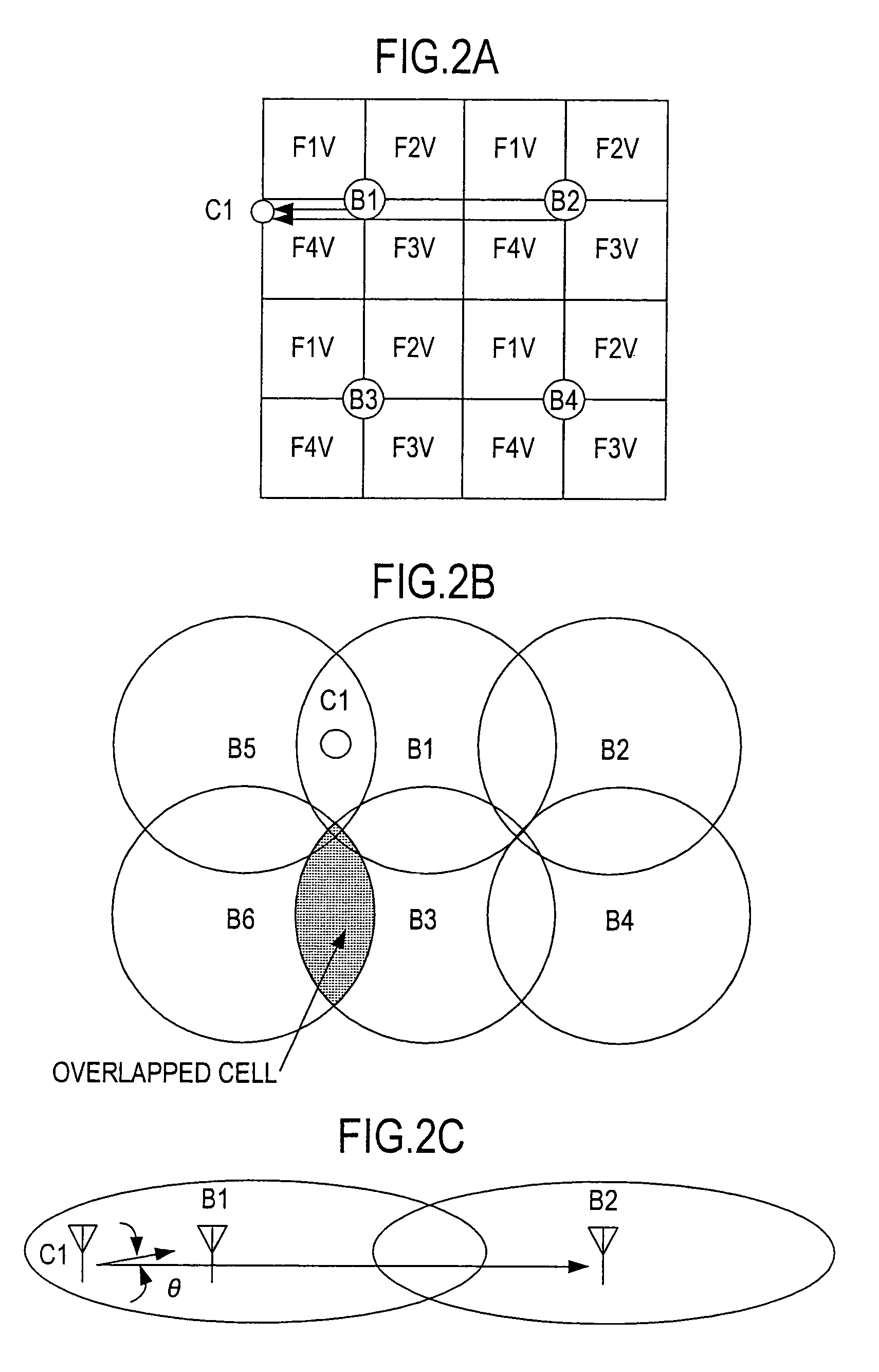
[0069]FIG. 2 consists of plan views showing the position of a subscriber station and adjacent base stations when interference occurs between them in the radio system according to the present invention. FIG. 2A is a diagram showing interference given by the subscriber station to the adjacent base stations or by the adjacent base stations to the subscriber station. FIG. 2B is a diagram showing actual service areas approximately circular in form with each base station at the center. FIG. 2C is a diagram showing an example of the position of the base stations and the subscriber station between which interference occurs.

[0070]When the base stations are arranged as in FIG. 1, what is expected is interference given by the subscriber station to the adjacent base stations or by the adjacent base stations to the subscriber station. This kind of interference occurs when two base stations fall in a beam width of the antenna at the subscriber station.

[0071]In general, since base stations are ins...

second embodiment

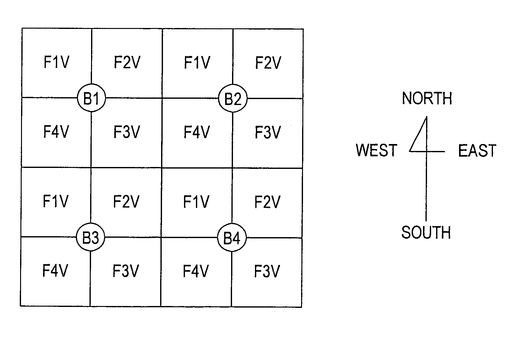
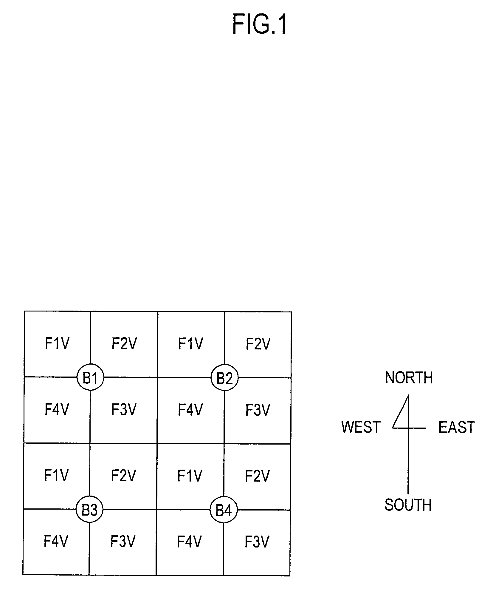
[0080]FIG. 4 is a plan view showing a layout of base stations in a radio system according to the present invention.

[0081]In FIG. 4, B1 to B4 are base stations, numerals following F denote frequencies used, and V or H following each numeral denotes the use of a vertically or horizontally polarized wave, respectively.

[0082]For example, all antennas at base stations using a vertically polarized wave at frequency F1 are arranged to face northwest. In other words, the base stations using the same frequency and the same polarized wave can never face each other, and therefore no interference occurs between the base stations as long as they have the ability to discriminate cross polarization of the antennas.

[0083]Further, since subscriber stations is aimed at the base station concerned, the subscriber stations using frequency F1 direct their antennas in a direction between the south and the east, that is, the antennas never face in the other directions.

[0084]It is apparent from this fact th...

third embodiment

[0093]As apparent from a comparison between FIGS. 5A and 5B, in the third embodiment the position of F1 and F2, and F3 and F4 are replaced with each other to prevent the use of the same frequency in the same area. However, the frequencies may be replaced in a way different from that of FIG. 5B, or the frequencies may not need to be replaced if the base stations have an enough cross-polarization ratio.

[0094]Further, the third embodiment showed the case where additional base stations are installed at about the same location as the existing base stations, but they may be installed with separation from the existing base stations.

[0095]Furthermore, the third embodiment described how to increase base stations using the horizontally polarized wave in the service area of the vertically polarized wave, but the vertically and horizontally polarized waves may be in inverse relation to each other. Furthermore, base stations using vertically and horizontally polarized waves may be mixed in the i...


PUM


Abstract

The present invention is to provide a radio system that enables effective reuse of a limited number of frequencies without the occurrence of interference between subscriber stations. In the radio system according to the present invention, each base station is divided into two or more sectors, each of which is provided with an antenna different in directivity on a horizontal plane. The antennas are so placed that the antenna beams cover all the directions on the horizontal plane as a whole, and all the antennas using the same frequency and polarized wave are so arranged to face in about the same direction.

Description

BACKGROUND OF THE INVENTION[0001]1. Field of the Invention[0002]This invention relates to a radio system that divides its communication area into two or more cells to permit frequency reuse among the cells. In particular, it relates to a radio system for use in communications providing high-speed communication service such as data and image transmission.[0003]2. Description of the Related Art[0004]There are some conventional wireless subscriber lines called WLL (Wireless Local Loop) and FWA (Fixed Wireless Access), LMDS (Local Multipoint Distribution Service). In such subscriber lines, one-to-multi directional radio equipment, called a P-MP (Point-Multi Point) system, is constituted of wireless transmission lines that connect base stations installed by a telecommunications carrier with many subscriber stations installed at users premises.[0005]This system installs two or more base stations in a certain region to provide service in all the parts of the region. In this system, however...

Claims


Application Information

Patent Timeline
Patent Type & Authority Patents(United States)
IPC IPC(8): H01Q1/24H04W16/02H04W16/12H04W16/24H04W16/28
CPCH01Q1/246H04W16/02H04W16/12H04W16/24H04W16/28
Inventor MURAMOTO, MITSURUSASAKI, KANEMIAOYAGI, YUJI
Owner KOKUSA ELECTRIC CO LTD
Why Eureka
Try Eureka