

Electrophysiology catheter
- Summary
- Abstract
- Description
- Claims
- Application Information
AI Technical Summary
Benefits of technology
Problems solved by technology
Method used
Image

Examples
first embodiment
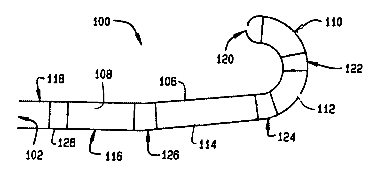
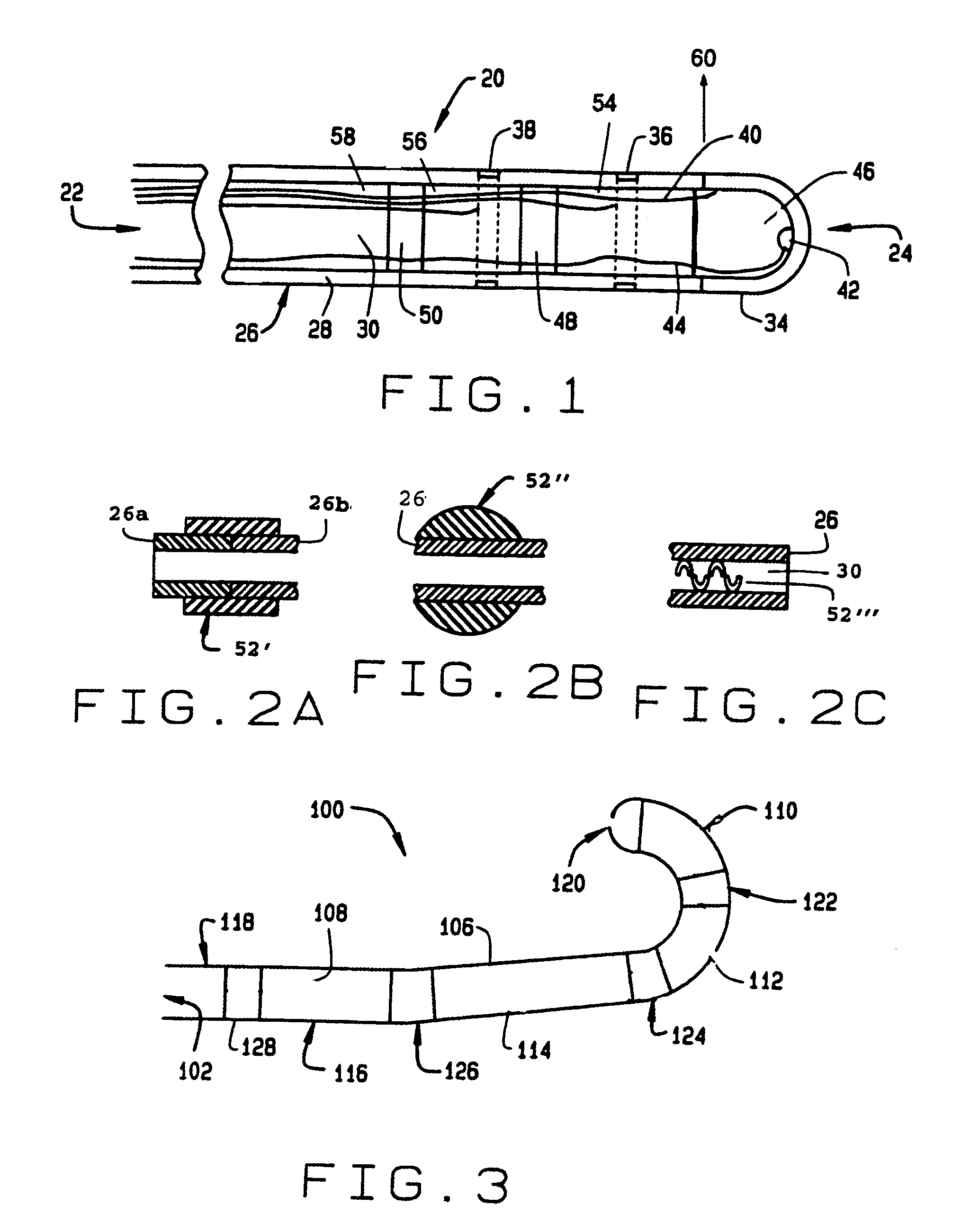
[0014]an electrophysiology catheter constructed according to the principles of this invention is indicated generally as 20 in FIG. 1. The electrophysiology catheter 20 has a proximal end 22 and a distal end 24. The catheter 20 preferably includes a hollow flexible tube 26 with a sidewall 28 and a lumen 30 therethrough. A longitudinal axis 32 extends generally through the lumen 30 in the center of the device. The tube 26 is preferably made from a flexible biocompatible materials such as Pebax™.
[0015]As shown in FIG. 1, the catheter 20 can have a dome-shaped end electrode 34 on its distal end, and one or more ring electrodes 36 and 38 which extend around the distal end portion of the tube 26. The ring electrodes may actually have a slit therein to reduce eddy currents when the catheter moves in an applied magnetic field. Lead wires 40 extend proximally from the electrodes 34, 36, and 38 to conduct electrical signals, from the electrodes to a signal processing unit at the proximal end ...
second embodiment
[0019]The magnetic members 46, 48, and 50 can take any size and shape, provided that they provide sufficient response to the applied magnetic field. As shown in FIG. 1, the magnetic members 4648, and 50 can be sized and shaped to accommodate the leads 40 and 44 within the lumen 30. A second embodiment includes sleeve shaped magnetic members 52′ (FIG. 2) which may be disposed anywhere on the outside of the tube 26. In the embodiment shown in FIG. 2, the sleeve shaped magnetic members 52′ have an inside diameter of between about 0.008 and 0.092 inches to receive the tube 26, and an outside diameter of between about 0.010 and 0.105 inches; and a length of between about 0.020 and 0.320 inches. The dimensions of the magnet 52′ will depend on the size of the tube 26 size, the tube material, catheter function, and the number of leads 40 and 44 in the lumen 30.
[0020]The sleeve-shaped magnetic members 52′ can also be used to aid in connecting tube sections 26a and 26b, as is illustrated in F...
PUM
 Abstract
Description
Claims
Application Information