Modular diluent changeover manifold for beverage dispensers

a beverage dispenser and module technology, applied in the direction of liquid dispensing, liquid flow controller, packaging, etc., can solve the problems of tedious and often expensive problems

Active Publication Date: 2006-01-03
CORNELIUS INC
View PDF1 Cites 8 Cited by
  • Summary
  • Abstract
  • Description
  • Claims
  • Application Information

AI Technical Summary

Benefits of technology

[0009]An object of the present invention is to provide a modular dual diluent changeover system for a beverage dispenser having a plurality of post-mix beverage dispensing

Problems solved by technology

As a result, reconfiguring a valve to dispense a different beverage required the tedious and often expensive task of reconfiguring the beverage delivery lines through discon

Method used


Image

  • Modular diluent changeover manifold for beverage dispensers
  • Modular diluent changeover manifold for beverage dispensers
  • Modular diluent changeover manifold for beverage dispensers

Examples


Embodiment Construction

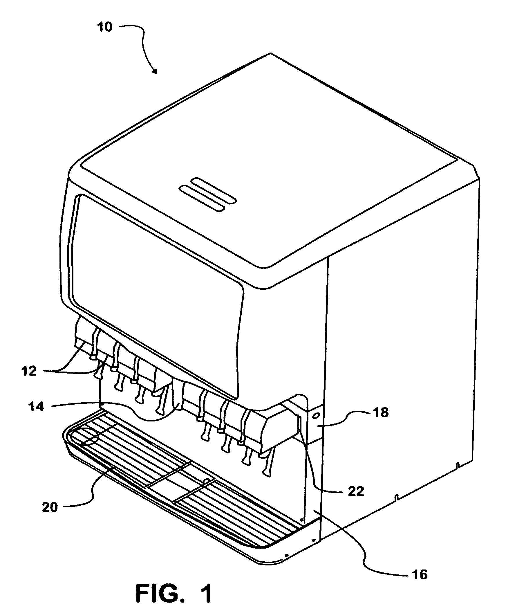
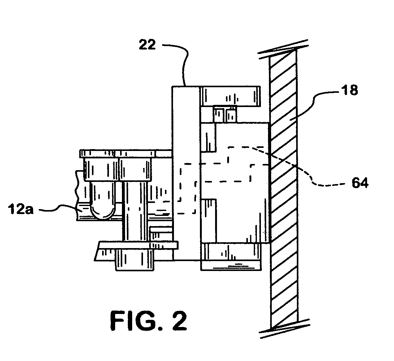
[0020]A changeover manifold and valve assembly according to the present invention is adapted for use with beverage dispensers, such as a post-mix ice / beverage dispensers of a type shown in FIG. 1 and indicated generally at 10. The dispenser 10 can be of the electrically cooled or ice cooled variety and includes a plurality (eight as shown) of post-mix beverage dispensing valves 12, a centrally located ice dispensing chute 14, a removable splash panel 16, a valve mounting panel 18 and a drip tray 20. To accommodate mounting of the post-mix dispensing valves 12 on the valve mounting panel 18, as seen in FIG. 2a body 12a of each dispensing valve is removably secured to an associated quick-disconnect mounting block 22 that in turn is carried by the valve mounting panel.

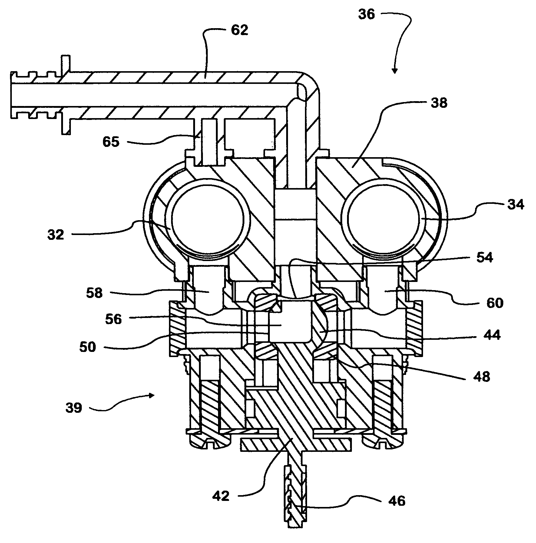
[0021]Referring also to FIG. 3, a changeover manifold and valve assembly is indicated generally at 30 and is located within the dispenser 10 behind the valve mounting panel 18. The changeover manifold and valve assembly 3...


PUM


Abstract

A modular diluent changeover manifold for beverage dispensers provides quick and convenient changeover of supply of two different beverage liquid diluents to post-mix beverage dispensing valves. The diluent changeover manifold is mounted within a beverage dispenser behind a beverage valve mounting panel. The modular changeover manifold and valve assembly, when assembled, consists of a pair of diluent tubes and a plurality of changeover valves. Each changeover valve has an outlet fluidly connected to an associated one of the beverage dispensing valves and each tube supplies a different diluent, such as plain water and carbonated water, to one of two inlets to each changeover valve. The changeover valves are individually manually manipulateable to deliver to their associated beverage valves either the diluent from the first tube or the diluent from the second tube.

Description

[0001]This application claims benefit of provisional application Ser. No. 60 / 469,516, filed May 9, 2003.FIELD OF THE INVENTION[0002]The present invention relates generally to beverage dispensing systems, and in particular to a modular diluent changeover system for beverage dispensers that allows for quick and convenient changeover between supply of carbonated water and plain water to beverage dispensing valves.BACKGROUND OF THE INVENTION[0003]Ice / beverage dispensers are often contained in a single cabinet, in an upper portion of which is an ice retaining hopper and in a lower portion of which is a cold plate. The cold plate is cooled by a volume of ice that is gravity delivered from a lower opening in the hopper into the lower portion of the cabinet and onto and in heat exchange contact with the cold plate. The cold plate provides for heat exchange cooling of beverage liquids flowed through tubing circuits embedded in the cold plate, which beverage liquids include mixing or diluent ...

Claims


Application Information

Patent Timeline
IPC IPC(8): B65D5/06B67D1/00B67D1/12
CPCB67D1/1247B67D2210/0006
Inventor TOBLER, ANDREW J.
Owner CORNELIUS INC
Why Eureka
Try Eureka