Self-clinching cable tie mount

a self-clinching, cable tie technology, applied in the direction of machine supports, furniture parts, other domestic objects, etc., can solve the problems of the tendency to dislodge itself over time from the sheet panel, the final placement of the adhesive backed mount on the panel is quite often inconsistent, and the adhesive backing fails quite often. , to achieve the effect of low profil

Inactive Publication Date: 2006-01-03
WINTON III GEORGE R
View PDF22 Cites 9 Cited by
  • Summary
  • Abstract
  • Description
  • Claims
  • Application Information

AI Technical Summary

Benefits of technology

[0012](d) to provide a self-clinching fastener used as a cable tie mount that

Problems solved by technology

The disadvantage of the Nicoli adhesive mount is its tendency to dislodge itself over time from the sheet panel.
The adhesive backing quite often fails when too much load is placed on the adhesive mount.
Also, the final placement of the adhesive backed mount on a panel is quite often i

Method used


Image

  • Self-clinching cable tie mount
  • Self-clinching cable tie mount
  • Self-clinching cable tie mount

Examples


Embodiment Construction

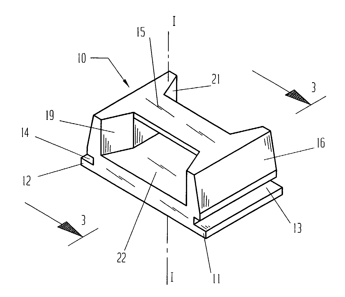
[0023]With initial reference to FIGS. 1 and 2, a self-clinching cable tie mount 10 is shown. Mount 10 has a body 15. Protruding outward and adjacent to body 15 are two extended lands 11 and 12. Extended land 11 and extended land 12 are set apart from one another. Both extended lands 11 and 12 are parallel to one another. Formed into body 15 are two undercut grooves 13 and 14. Undercut groove 13 and extended land 11 are adjacent and parallel to one another. Undercut groove 14 and extended land 12 are adjacent and parallel to one another. Body 15 joins extended lands 11 and 12 with undercut grooves 13 and 14.

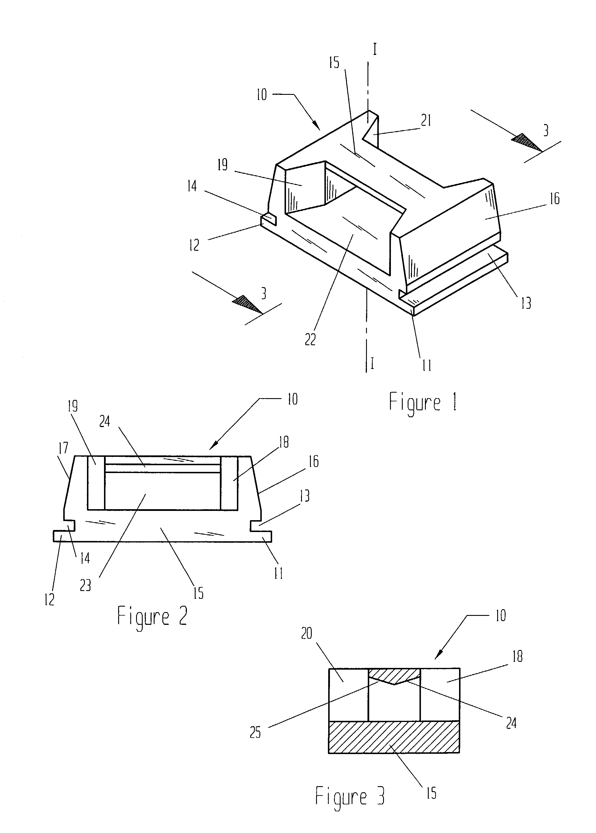
[0024]From FIG. 2, body 15 has an external guide wall 16 that is adjacent to undercut groove 13. An external guide wall 17 is located on body 15 and opposite in side to external guide wall 16. External guide wall 17 is adjacent to undercut groove 14. Both external guide walls 16 and 17 slope inward and away from undercut grooves 13 and 14.

[0025]From FIGS. 1 through 3, a cavity 23 ...


PUM


Abstract

A self-clinching fastener that when pressed into a thin sheet panel provides for a strong attachment point for a cable tie. The inventive fastener relies on the self-clinching process to carry external loads and thus carries larger loads when compared to adhesive backed cable tie mounts. When installed, the self-clinching fastener becomes flush with the far side of the sheet panel.

Description

[0001]This application is a CON of application Ser. No. 10 / 028,281, filed Dec. 28, 2001, now abandoned, which is a CON of application Ser. No. 09 / 618,609, filed Jul. 17, 2000, now U.S. Pat. No. 6,367,745.BACKGROUND—FIELD OF THE INVENTION[0002]The present invention relates to self-clinching fasteners that provide for a secure mounting location for common cable ties.BACKGROUND—DESCRIPTION OF PRIOR ART[0003]Manufacturers of industrial machines quite often make use of wire harnesses to distribute electrical power to various locations within a machine. It is common to run bundles of wire along a sheet metal panel in order to distribute the bundles of wires. These bundles are often anchored to a sheet panel in discreet locations to prevent the wires from coming in contact with harmful elements.[0004]A common approach to anchoring these wire bundles to a panel makes use of a plastic molded cable mount with an adhesive backing. Examples of an adhesive backed cable tie mount is disclosed by ...

Claims


Application Information

Patent Timeline
IPC IPC(8): A47B97/00F16L3/233
CPCF16B11/002F16L3/24F16L3/233F16L3/243
Inventor WINTON, III, GEORGE R
Owner WINTON III GEORGE R
Why Eureka
Try Eureka