
Vehicle engine starting apparatus

a technology for starting apparatuses and vehicles, applied in anti-theft devices, relays, transportation and packaging, etc., can solve the problems of inferior operation, difficult coordination of rotational switches with the switches of electrical devices in the center cluster, and difficulty for right-handed drivers to manipulate switches

Inactive Publication Date: 2006-01-03
KK TOKAI RIKA DENKI SEISAKUSHO
View PDF13 Cites 21 Cited by
  • Summary
  • Abstract
  • Description
  • Claims
  • Application Information

AI Technical Summary

Benefits of technology

[0009]Accordingly, it is an objective of the present invention to provide an engine starting apparatus that clearly shows the location of an engine start switch.

Problems solved by technology

If the rotatable switch is arranged in the center cluster of the instrument panel, the operability is inferior to a case in which the switch is provided on a side of the steering wheel that faces the driver's seat.
For example, if the rotatable switch is provided in the center cluster of a car with a right-hand steering wheel, a right-handed driver has difficulty manipulating the switch since the driver has to use the left hand.
Also, it is difficult to coordinate rotational switches with the switches of electrical devices in the center cluster.
This adversely affects the appearance of the center cluster.
Therefore, for occupants of the vehicle, the switches are not easily distinguished.

Method used


Image

  • Vehicle engine starting apparatus
  • Vehicle engine starting apparatus
  • Vehicle engine starting apparatus

Examples


first embodiment

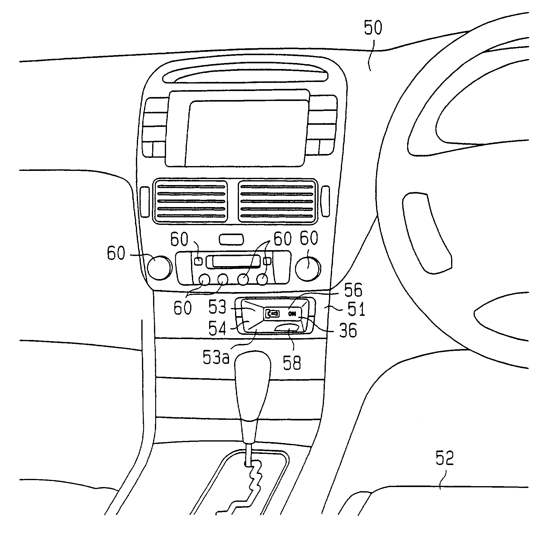
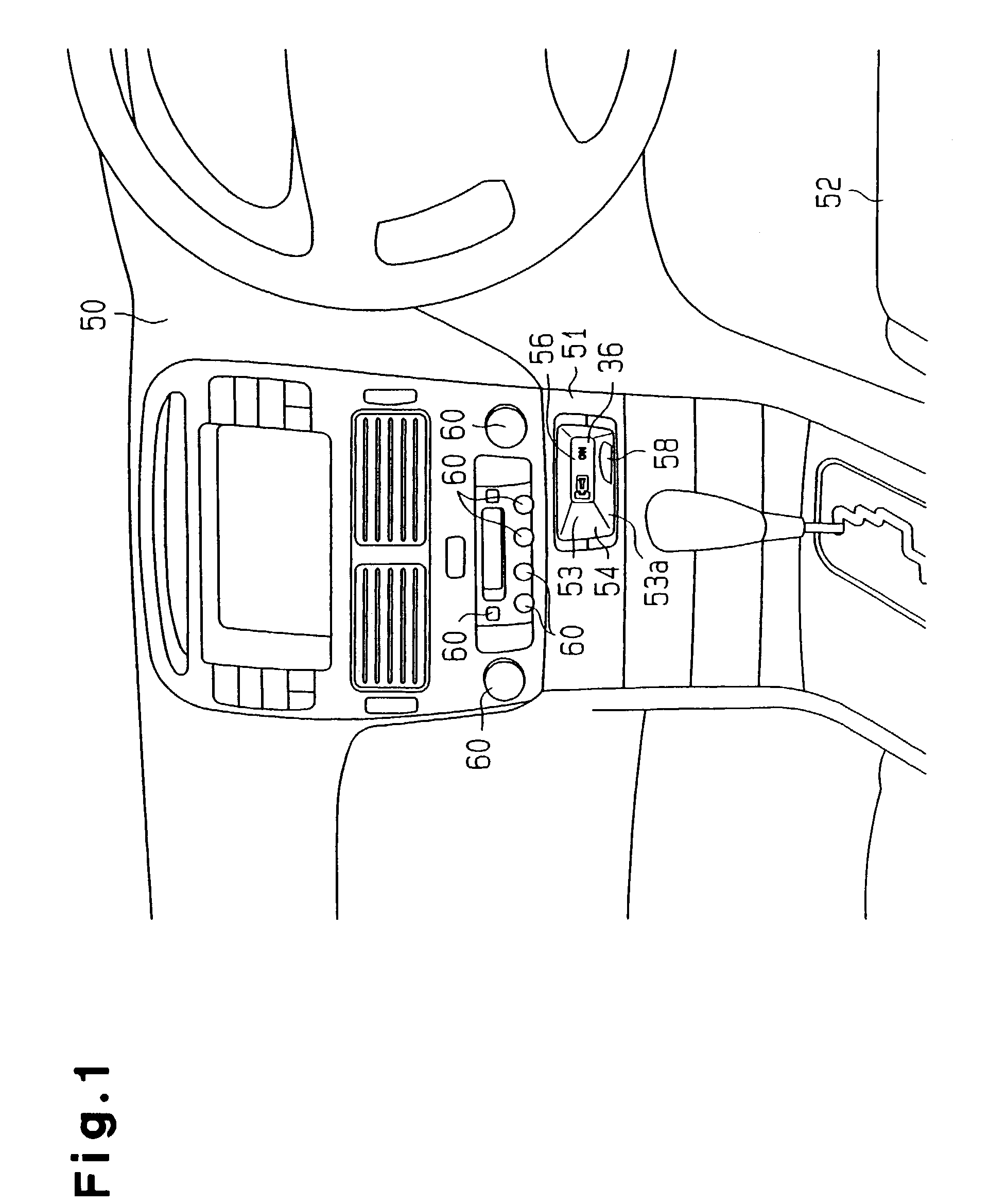
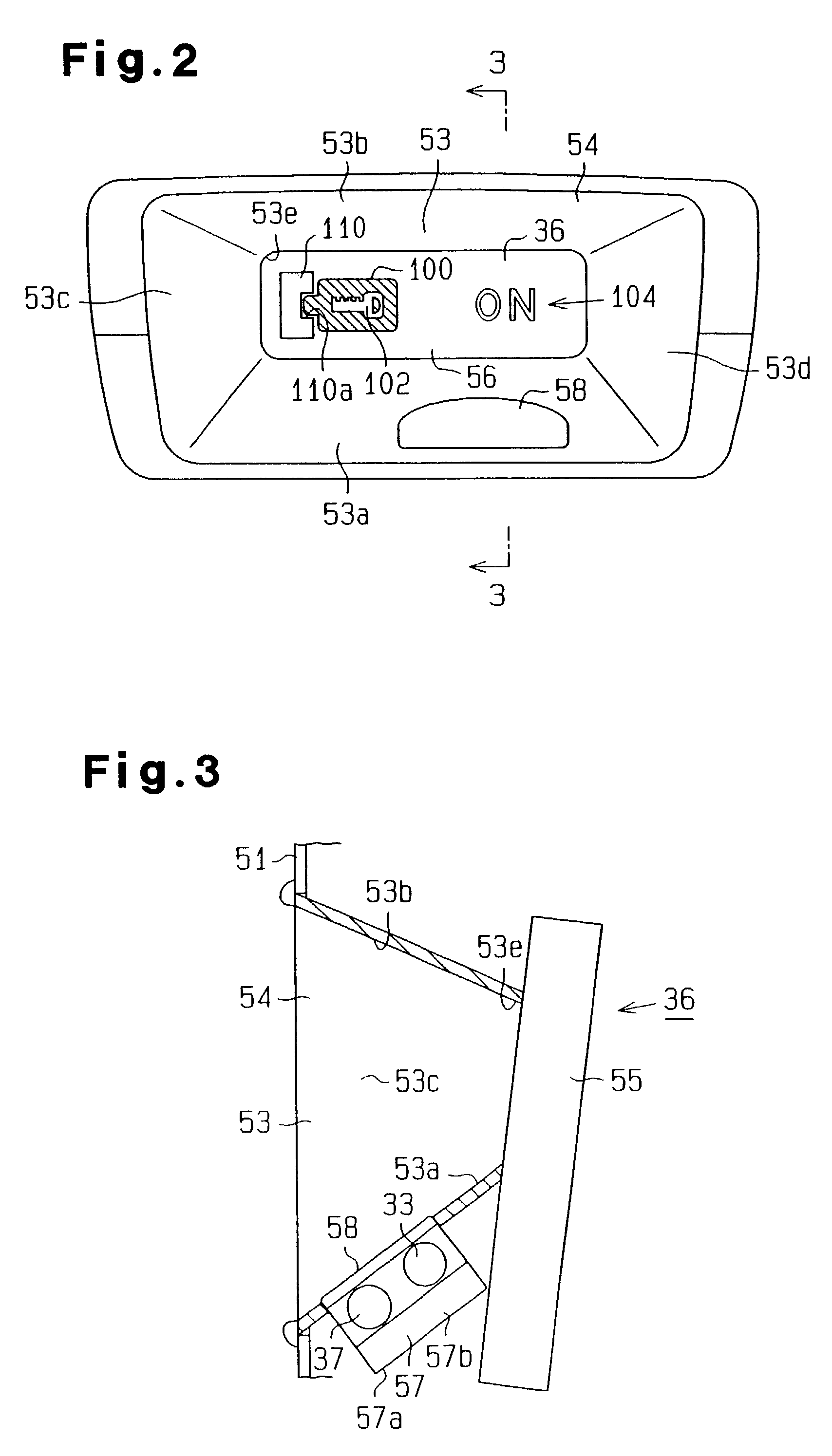
[0098]A vehicle engine starting apparatus 1 according to the present invention will be described with reference to FIGS. 1 to 13.

[0099]As shown in FIG. 4, the engine starting apparatus 1 includes a portable communication device 11 carried by an occupant (driver) of a vehicle 2, and a communication controller 12 mounted on the vehicle 2. The portable communication device 11 includes a reception circuit 13, a microcomputer 14, a transmission circuit 15.

[0100]The reception circuit 13 receives a request signal from the communication controller 12 and passes the request signal to the microcomputer 14. When receiving a request signal from the reception circuit 13, the microcomputer 14 outputs a transmission signal (ID code signal) containing a predetermined ID code. The transmission circuit 15 modulates the ID code signal to radio waves having a predetermined frequency and transmits the radio waves to the outside. The reception circuit 13 and the transmission circuit 15 are connected to a...

second embodiment

[0259]the present invention will now be described with reference to FIGS. 14(a) and 14(i), and FIGS. 15(a) to 15(d).

[0260]In the following embodiments, the differences from the embodiment of FIGS. 1 to 13 will be mainly discussed, and like or the same reference numerals are given to those components that are like or the same as the corresponding components of FIGS. 1 to 13.

[0261]This embodiment is the same as the embodiment of FIGS. 1 to 13 except for the first to fifth display modes and the seventh to tenth display modes.

[0262]As shown in FIGS. 14(a) to 14(i) and FIGS. 15(a) to 15(d), the key hole icon 110 is omitted from the first to fifth display modes and the seventh to tenth display modes.

[0263]Instead of showing the key frame icon 100 being inserted into the key hole icon 110 as described above, a substantially rectangular holding frame 108 surrounding the key frame icon 100 is shown. The holding frame 108 corresponds to a second display image.

[0264]Particularly, the fifth dis...

third embodiment

[0272]the present invention will now be described with reference to FIGS. 16 to 21, and 23(e).

[0273]In this embodiment, the control flowchart of a control program executed by the microcomputer 24 is different from the embodiments of FIGS. 1 to 15(d). Hereinafter, the differences from the embodiments of FIGS. 1 to 15(d) will mainly be discussed, and the same reference numerals are given to those steps that are the same as the corresponding steps in the embodiments of FIGS. 1 to 15(d).

[0274]In this embodiment, the control program executed by the microcomputer 24 is basically the same as the program shown in FIG. 8.

[0275]FIG. 18 is a verification process routine of this embodiment.

[0276]1. Verification Process Routine.

[0277]In this embodiment, steps S140, S150, S180 are omitted from the control flowchart of FIG. 9. Since step S150 is omitted, the ACC relay 41 is not automatically activated unlike the first and second embodiments.

[0278]In step S130, based on the verification result in s...


PUM


Abstract

A vehicle engine starting apparatus has an engine start switch, a display device and a microcomputer. The display device shows the location of the start switch. The microcomputer identifies a specific signal, and controls the display device in accordance with the result of the identification executed by the microcomputer.

Description

BACKGROUND OF THE INVENTION[0001]The present invention relates to a vehicle engine starting apparatus.[0002]In recent years, there is a demand for an improved operability of vehicles in addition to demands for improved basic performances and safety of vehicles. For example, a vehicle engine starting apparatus called “smart ignition” system has been proposed. The smart ignition system enables a driver to start and stop the engine of a vehicle without using keys.[0003]A typical vehicle engine starting apparatus includes a portable communication device carried by an occupant such as a driver of a vehicle, a communication controller mounted on the vehicle, and an engine start switch (ignition switch) provided in the passenger compartment (for example, a side of a steering wheel that faces the driver's seat). When the driver gets in the vehicle, an ID code assigned to the communication device is automatically checked against an ID code assigned to the communication controller. If the ID ...

Claims


Application Information

Patent Timeline
IPC IPC(8): B60R25/10B60R25/02B60R25/04B60R25/20B60R25/24
CPCB60R25/02B60R25/24B60R25/2063B60R25/04
Inventor NAGASAKA, CHIKAONAKAMURA, TORUISOGAI, TOSHIYUKIKISHIDA, SHINJI
Owner KK TOKAI RIKA DENKI SEISAKUSHO
Learn More